(pressing HOME will start a new search)
![]()
![]()
- ASC Proceedings of the 28th Annual Conference
- Brigham Young University-Provo, Utah
- April 18-20, 1991 pp 29-36
|
(pressing HOME will start a new search)
|
|
USE OF COMPUTERS FOR DEVELOPMENT OF MANAGEMENT SKILLS IN A REINFORCED CONCRETE DESIGN COURSE
|
|
Construction
educators are criticized for ineffective teaching of structural design
courses. A Management Skill Building (MSB) approach may be used to
integrate computer use with assignments in a first course in reinforced
concrete design. Students may use a spreadsheet to solve problems such
as bar development length, beam analysis, column analysis and beam
deflection. Student understanding of basic principles and general
problem solving ability is enhanced. MSB principles maybe applied to
other construction science courses. KEY
WORDS:
Management skills,structural design, reinforced concrete,
spreadsheets. |
INTRODUCTION
Much
discussion has been directed at the problem of teaching design courses and
specifically at the problem of teaching structural courses in construction
degree programs. Criticism aimed at courses in concrete, steel, timber and
foundations cite an overemphasis on design and a lack of a construction
management perspective. In response to concern for building communication
skills, some construction educators increased requirements for oral and written
reports in construction science courses. A similar approach utilizing computers
as the tool may be used to enhance teaching of management skills in structural
design courses. By designing computer solutions to problems, students are forced
to clearly understand basic concepts of design. Designing a computer solution to
a problem requires planning the appropriate calculations, properly sequencing
the calculations and anticipation of possible answers for different given
values. The management, decision-making and productivity skills learned may be
applied in other courses and in future management careers in construction.
The
construction degree program at Northeast Louisiana University includes a
computer application course taught by the computer science department which
includes BASIC programming language, a spreadsheet, word processor and a
database program. Students are expected to gain a working knowledge of current
software. Incorporating software usage into construction science classes
increases opportunities for students to build management skills in problem
solving while receiving instruction from an expert on the topic.
The
computer spreadsheets included in the Appendices perform tedious calculations in
reinforced concrete design. The work was assigned to students in a reinforced
concrete design course taught at the School of Construction, Northeast Louisiana
Univer�sity in Monroe, Louisiana.
TEACHING METHOD
Selected
problems called Management Skill Builders (MSBs) were assigned. The problems
selected were beam analysis, bar development length, column analysis and beam
deflections. The MSBs were developed on personal computers using Lotus 1-2-3TM
spreadsheets. Spreadsheets are generally easier to learn than high level
computer languages and have built-in printing, formatting, editing and file
handling utilities. A hard copy example of an acceptable solution format was
provided to show students the required information and a reasonable format for
display of the solution. Corresponding homework assignments with calculations
performed by hand were assigned and graded. Comparison with the hand
calculations provided additional help in development of MSBs. Students were
required to turn in diskettes and hard copy solutions to the problems. One class
period was used for computer orientation. Students were encouraged to seek help
from a manual and from other students.
The
MSBs described in this paper draw largely from reference [1]. This paper is not
intended as a primer on reinforced concrete. Symbols used are the same as found
in ACI 318 and most basic texts on reinforced concrete design except for special
symbols used in reference [1]. A legend of symbols is included. For a more
detailed explanation of the problems see references [1] and [2].
THE
MANAGEMENT SKILL BUILDERS Appendices A,
B, C and D are output of the MSBs. User supplied information is surrounded by a
double box.
Basic Development Length
The
MSB created a table for manual "look-up" of information. The table
shown in Figure 1 is for non-top bars in tension and normal density concrete.
The students were required to use "IF' statements in the spreadsheet to
select the correct equation among four choices for calculation of the tabulated
data. The management skill taught was production of tabular reference materials.
Possible variations on the MSB are tables for Class A, B and C splice lengths,
top bars, bars in compression and deformed wire.
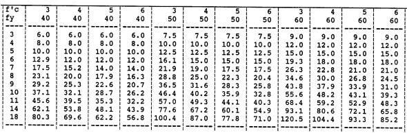 |
| Figure
1.
Development Length
BASIC DEVELOPMENT LENGTH OF NON-TOP BARS IN TENSION; NORMAL DENSITY
CONCRETE |
Singly-Reinforced Rectangular Beam
Producing
the beam analysis MSB (Figure 2) required application of equations for flexural
design by the load factor method for a simple, singly-reinforced concrete beam.
Steel ratios that violated American Concrete Institute (ACI) code requirements
were "flagged". By substitution, the flexural capacity of beam cross
sections may be checked. The management skill taught was development of a design
aid for use as an alternative to traditional methods developed for slide rules
and hand calculators. Variations of the MSB could include a "look-up"
table to check rebar spacing or a MSB for doubly reinforced beams and tees.
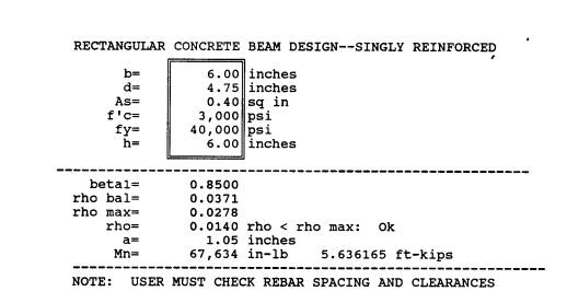 |
| Figure
2.
Singly-Reinforced Rectangular Beam |
Column
Anal,
The
column analysis MSB (Figure 3) analyzes short rectangular columns with
symmetrical cross-sections in strong-axis bending. The balanced failure
condition, column load capacity and failure mode were determined. Possible
failure modes are: (1) compressive failure, (2) tension failure with yielding of
compression steel and (3) tension failure with yielding of tension steel.
Traditional manual solution methods treat cases l, 2 and 3 separately.
Simplifying assumptions allow direct solutions for cases 1 and 2. Case 3 may
only be solved by a tedious trial and error solution because of a cubic equation
for the location of the neutral axis. However, the trial and error solution for
case 1 also solves case 2 and 3. By varying the column eccentricity, column
interaction diagrams may be manually constructed. Development of the MSB
requires planning and sequencing of calculations. The management skill taught
was reduction of tedious trial and error calculations to manageable problems.
Variations of the MSB could include biaxial bending and rebar spacing checks.
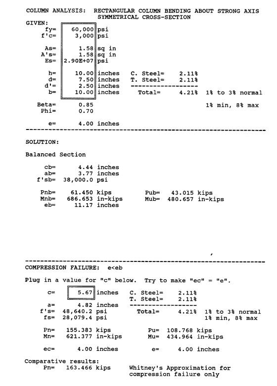 |
| Figure
3.
Column Analysis |
Beam Deflection
The
beam deflection MSB (Figure 4) calculates maximum dead and live load deflections
for simply supported rectangular, singly-reinforced concrete beams with uniform
dead and live loads. A major difficulty in beam deflection calculations is
likely to be accurate determination of loads. A notable difference between
reinforced concrete beams and steel or timber beams is that reinforced concrete
beams crack. While the same basic deflection equations for elastic bending are
used, the moment of inertia may vary due to beam cracking under load. The MSB
must be designed to determine the correct moment of inertia to use with the load
under consideration. The management skill taught was allowance for varying
conditions in analysis. Variations of the MSB could include doubly-reinforced
beams, deflections at varying locations on the beam and comparison of deflection
calculations to ACI limits. The dead load (DL) given for the beam in Figure 4
corresponds to the beam weight. The live load (LL) is zero. The given beam was
built in the laboratory portion of the course to verify the deflection
calculations.
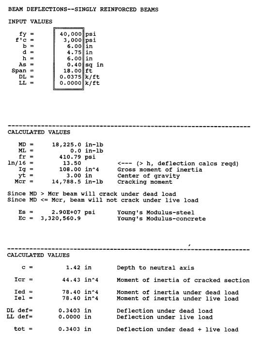 |
| Figure
4.
Beam Deflection |
FUTURE
DEVELOPMENT
Additional
MSB units in reinforced concrete may be developed for shear, torsion, crack
control and footings. The MSB method has been used by the author in estimates
(quantity take-off), statistics, strengths of material, surveying and concrete
mix design.
DISCUSSION
Construction
management students in structural design courses have different expectations and
goals than design students. Construction managers must learn to communicate
effectively with design professionals on a wide variety of topics and an
appropriate level of technical detail in order to increase quality and
productivity of work.
When
judgment is required in making a management decision, memorized solution
procedures are not as valuable to construction management students as an
understanding of basic design principles.
In
order to develop the appropriate algorithm for problem solutions with a computer
spreadsheet, students must thoroughly understand problem solution procedures.
Students must anticipate the possible range of answers and build in necessary
checks for possible errors.
Spreadsheets
are easy to learn and have many desirable built-in utilities that increase
productivity. Students may use spreadsheets to perform "what if' analysis
in structural design. Spreadsheet problem solving skills may be applied in other
management areas such as estimating.
Design
professionals may choose from a variety of commercial software packages.
Customized computer programs are frequently written in high-level computer
languages such as BASIC, PASCAL, FORTRAN, C or database languages. These
programs may be the most efficient tools for design professionals, but do little
to reinforce understanding of basic principles when used by students. MSBs could
be written in high-level languages, but high-level languages generally take
longer to learn and require greater programming time. A construction manager can
rarely justify the use of management time for development of software. For the
manager, spreadsheets are the medium of choice.
CONCLUSIONS
1.
The MSB units are an effective method for incorporating computer and management
skills into a construction science course in reinforced concrete. 2. The
exercises used in the class are best suited for solution with computer
spreadsheets such as Lotus 1�
2-irm
or Quattro.
3.
Depending on students' computer skills and facilities available, one to four
MSBs could be used in a first course in reinforced concrete design.
REFERENCES
|
Everard,
N. J. and Tanner, J. L., Reinforced Concrete Design, Second
Edition, Schaum's Outline Series, New York: McGraw-Hill, Inc., 1987. Nawy,
E. G., Reinforced Concrete: A Fundamental Approach.
Englewood Cliffs, New Jersey: Prentice-Hall, Inc., 1990. |
LEGEND
|
As
Area of tension steel, in2 (crri ) A's
Area of compression steel, in2 (crr? ) DL
Dead load, K/ft (kN/M) Ec
Young's modulus for concrete, psi (N/mn2 ) Es
Young's modulus odulus for reinforcing steel, psi I
Moment of inertia of section, ina (mma) LL
Live load, K/ft (kN/M) MD
Moment due to dead loads, in-lb (kN-M) ML
Moment due to live loads, in-lb (kN-M) Mn
Nominal moment of resistance of section, in-lb (kN-M) a
Depth of, compressive stress block in Whitney equivalent stress
block model, inches (mm) b
Beam width on compression side, inches (mm) beta
1 Stress
block depth factor c
Depth from extreme compression fiber to neutral axis, inches (mm) d
Depth of beam from extreme compression fiber to centroid of steel
area, inches (mm) d'
Depth of beam from extreme fiber to centroid of compression steel,
inches e
Eccentricity of load to plastic centroid, inches (mm) fc
28-day compressive strength of concrete, psi (MPa) fy
Yield strength of steel, psi (N/mm2) fr
Modulus of rupture of concrete, psi (MPa) fs
Stress in tension steel, psi (N/ mm2) h
Total depth of beam, inches (mm) Id
Basic development length of rebar, inches (mm) In
Span, inches (M) Phi
Strength reduction factor Rho
Reinforcement ratio rho
bal
Reinforcement ratio for balanced section rho
max Maximum
permissible reinforcement ratio yt
Distance from extreme compression fiber to plastic centroid, inches
(mm) |
Subscripts
|
cr
Indicates property of a cracked section e
Indicates effective properties g
Indicates gross section properties n
Indicates condition due to strength reduction factor, phi u
Indicates condition due to external factored loads |