- ASC Proceedings of the 42nd Annual Conference
- Colorado State University Fort Collins, Colorado
- April 20 - 22, 2006
|
|
|
The Feasibility of Generating and Using Rapid Prototype Architectural Models in a Construction Program
|
Dr. Gary J. Winek, Ph.D., and Mr. Robert C. Tisdel, M. Arch Texas State University-San Marcos San Marcos, Texas |
|
This article summarizes the preliminary results of building architectural models using a Stratasys, Fused Deposition (FDM) 3000, Rapid Prototyping (RP) machine. Described in the paper is the value of architectural models in a construction program. Also mentioned are the steps needed to create the necessary three-dimensional CAD data, saving the data in the required .stl file format and the rapid prototyping process used to generate the models. Limitations of the RP process in terms of size, scaling, cost and time to build the models are presented along with future research to improve the quality of the RP models.
Key words: Rapid Prototyping, Fused Deposition Modeling, Architectural Models, Computer-Aided Design |
Introduction
Architectural modeling using Rapid Prototyping (RP) may seem like a topic more suited for architectural schools than construction programs. However, as owners demand increasingly complex construction projects to be completed in shorter periods of time, the use of RP in the concept, design, constructability, and scheduling phase will become more important to reduce both time and building costs. Also, the process will see increased use in the construction field as RP machine costs decline and more construction programs introduce the process to their students. It is the author’s opinion that it is not a question of will RP be used in the construction industry, but when and to what extent.
Why Use Rapid Prototyping for Models
A three dimensional model has always been important to an owner for visualization purposes before committing millions of dollars to constructing a project. It has been said that if a picture is worth a thousand words, then a model is worth a thousand pictures (Jacobs, 1992). Therefore, models are important in construction and RP is an emerging new technique for their creation. Since there are no geometric limitations to the RP process, more sophisticate models can be built than is possible by building traditional models by hand. Also, the emerging trend in Architecture is to use free form designs which are better visualized using models versus a 2-D paper representation of the form (Bui, 2006).
RP can, in most cases, build more accurate models than is possible by traditional architectural model making techniques. Therefore, RP holds the promise of creating actuate 3-D models automatically. This would allow students to build models of their designs without having to be trained in the art of model making and then devoting time to actually construct the model itself.
The RP, CAD Requirements
The RP process requires that the model to be built must be derived from true three dimensional (3-D) CAD data, which must be saved in an .stl (also known as stereolithography) format. It is the .stl file that will be used by the RP machine’s software to create the necessary machine language to build the model. Therefore, it is necessary for students to create their drawings using 3-D CAD software, which is becoming more common in the construction industry, such as Autodesk’s Architectural Desktop software. However, Autodesk’s new construction software package called Revit is designed as a 3-D Architectural package from the ground up. Not only will Revit allow students to draw in 3-D and generate the needed .stl files, but it can also generate a real-time material list. Again it is believed by the authors that the transition from 2-D drawing to 3-D drawing in construction is only a matter of time.
Creating the 3-D Digital Drawing
The majority of CAD users today work with a software package known as AutoCAD. AutoCAD commands a lion’s share of the computer-aided design software market and works well with rapid prototyping. Let us take, for example, an architectural building project created in AutoCAD and work through the steps that are required to create the end result of a rapid prototyping model.
First, as a design is being constructed within the AutoCAD software, the operator must be aware that anything that is to be drawn and modeled by a rapid prototyping machine must be a three-dimensional solid. In the AutoCAD environment, there are a number of ways that one can create a three-dimensional solid. The initial design can be drawn in a two-dimensional format and then converted or “extruded” to three-dimensions. However, a design that will be solidified using rapid prototyping will more likely be created in three-dimensions from the beginning. The AutoCAD software offers a number of different solid forms that can be created and edited, added or subtracted from one another, and then unioned together to form a final digital model. This latter form of editing known as “unioning” or the literal use of the “union” command in AutoCAD, is the final step in bringing together all of the separate three-dimensional forms to become one whole. Rapid prototyping requires that the entire digital model be one whole and that all of the parts that make up the whole be connected in some way. Once the model is completed, it should be placed in a positive X, Y, Z position. Although the geometry of the object is not limited, due to the nature of the rapid prototyping process, thin cross sections that are approaching the resolution of the RP machine should be avoided.
Second, when the digital model has been completed as one object, it must be saved as a specific file format. The standard file format used to specify the geometric shape of the part to be modeled is the .stl file format. In AutoCAD, the command, “STLOUT” can be used to start the conversion process. An .stl file can also be created using the “export” option from the “file” pull-down menu and then choosing “.stl (lithography)” format. Once the .stl conversion process is started, select the object, choose the “binary” format (compacted format), and then choose a file name. Once the CAD file is saved as an .stl file, it is ready to be used by a rapid prototyping machine. Although the process from CAD to .stl is relatively straightforward, once in the .stl format no further geometrical editing of the CAD file is possible.
The RP Process
The department obtained a Stratasys, FDM (Fused Deposition Modeling) 3000 RP machine on a National Science Foundation (NSF) grant in 1998 for a cost of $100,000. The machine was primarily used in the manufacturing program as a mechanism to reduce time-to-market cycles. Since most of the architectural drafting/design done in the department at the time was 2-D, there was no need for construction models. However, with the construction program’s theme shifted to design-build and the introduction of 3-D CAD into the architectural design three-course sequence, RP models now are a reality.
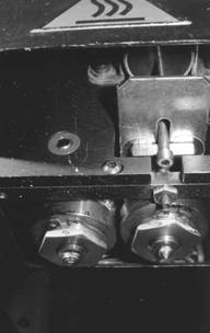
The Stratasys FDM 3000 machine has an X, Y, Z build envelope of 10” x 10” x 16” and it builds models through an extrusion process using Acrylonitrile Butadiene Styrene plastic, better known as ABS. The process starts by importing the .stl file of the model to the RP host computer. The .stl file’s geometric features cannot be altered, but the model can be scaled up or down in size and rotated for maximum model building efficiency. After proper scaling and orientation, the FDM machine’s software generates the slice files, support material geometry, and the machine paths necessary to build the model. This information is then transferred to the RP machine’s programmable logic controller (PLC). The machine has two extrusion nozzles (Figure 1). The .012” diameter nozzle on the left extrudes the ABS plastic in .010” high by .030” wide layers and is extruded at 290° centigrade. The .012” diameter nozzle on the right extrudes the water-soluble release which is used to build the base for the model and the necessary supports for any model over-hangs. This nozzle is heated to 235° centigrade. Once the two nozzles are cleaned, purged, and the build envelope reaches 70°C the model building process can begin.
|
|
|
Figure 1: Stratasys, FDM 3000 extrusion head showing ABS model building nozzle on left and water soluble support material nozzle on the right. |
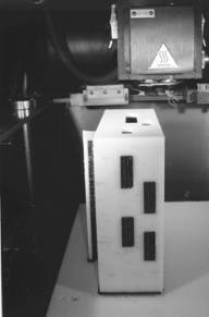
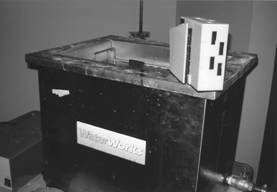
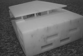
The model building begins by manually setting the support nozzle about .020” into the foam base. Then the pause or start button is pushed and the model building is automatic from this point. Note in Figure 2, the foam block at the bottom of the picture upon which the model thin support base is built (dark color). The white ABS plastic is the model. Also note how the dark support material is present in the four vertical windows on the front of the model. The model shown took 108 hours to build and weighed 1.75 pounds. After removing the model from the machine, it is separated from the foam base using a putty knife. Then the model was inserted into an 11 gallon, heated (65°C) ultrasonic tank which contains a solvent for about two hours (Figure 3). This process removes the support material leaving only the ABS model (Figure 4) which now weighs .61 pounds. The cost of the ABS plastic and also the support material is $150 per pound when purchased from the manufacturer. Therefore, the cost of both the ABS and support material to build the model was about $225.00.
|
|
|
Figure 2: Note foam base at the bottom of the picture with dark colored water-soluble support material and white color ABS model material. The extrusion head is in the background. |
|
|
|
Figure 3: Ultrasound bath used to dissolve the water-soluble support material |
|
|
|
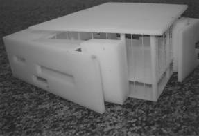
Figure 4: ABS model which took 108 hours to build. |
Figure 5 shows the backside of the model. Note how the curtain wall window mullions appear very thin. While in scale with the building model, the mullions are approaching the resolution of the machine. Scaling was the biggest problem encountered by the authors. This is because it is usually not feasible to build a model at common architectural or engineering scales. A scale, for example the common residential scale of ¼” = 1’, has two disadvantages when building RP models. The first is the complete model usually would not fit in the 10” x 10” x 16” build envelope of the machine and secondly, the machine time and material required to build the model is not realistic. Therefore, scaling the model by 50% or more may be necessary. That means a 6” thick wall at a ¼” = 1’ scale would be modeled at a 1/8” or .125” thick. If the model is scaled by 50%, the 6” thick wall would be modeled at 1/16” or .0625”. This dimension is very close to the .010” high by .030” wide extrusion width of the machine.
|
|
|
Figure 5: Note curtain wall window mullions on the right side of the model have reached the practical resolution of the FDM 3000 modeler. |
It has been suggested that scaling up thin sections of a model in relationship to the model as a whole, is a possible solution. While this solution would certainly solve the problem of thin sections, it would create features that are not in proper scale with the rest of the model. This could create a problem in Figure 5 by making the curtain wall window mullions appear more like columns than 4” wide mullions. Therefore, maintaining the same scale for the entire model is a necessity in almost all cases.
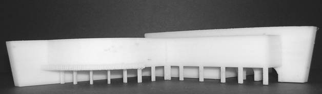
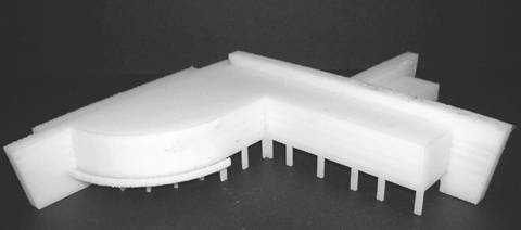
Figures 6 and 7 show a concept model built at an appropriate scale. This model took 66 hours to construct with material costs of about $234.00.
|
|
|
Figure 6: Model built at an appropriate scale requiring 66 hours to build. |
|
|
|
Figure 7: Alternate view of model in Figure 6. |
Conclusion
The biggest problem encountered with initial attempts to build RP architectural models was with scale. This problem was largely solved with the model shown in Figure 6 and 7. In the future, attempts to experiment with building scale models in parts and assembling them into larger models will be tried. Hopefully this method will provide a practical means of building larger scale models where smaller features such as the window mullions shown in Figure 5 are practical.
The advantage of RP models is that it allows construction students a practical method of modeling construction designs, especially free-form designs, without being a master model maker. These models can then be used to discuss design details, constructability of a design, and how to schedule the project. Currently, the material cost to build the models is affordable, but our Stratasys FDM 3000 machine, which costs $100,000, is not. However, costs are rapidly dropping on RP machines, and Stratasys, along with other manufacturers, currently offers a desk-top model for around $20,000.
It is the conclusion of the authors that with 3-D Architectural CAD becoming more available and RP machine costs falling, it is inevitable that the two will come together for use in the construction industry.
Citation Table of Contents
Bui, H.L. (2006, January 2). Translating AutoCAD architectural drawings into rapid prototyping compatible drawings. [WWW document]. URL http://www.msoe.edu/reu/BuiPaper.doc
Clough, R. H., Sears, G. A., & Sears, S. K. (2005). Construction contracting: A practical guide to company management. Hoboken, NJ: John Wiley and Sons, Inc.
Jacob, P. F. (1992). Rapid prototyping and manufacturing: Fundamentals of stereolithography. Dearborn, MI: Society of Manufacturing Engineers.