(pressing HOME will start a new search)
![]()
![]()
- ASC Proceedings of the 25th Annual Conference
- University of Nebraska-Lincoln- Lincoln, Nebraska
- April 1989 pp 68-73
|
(pressing HOME will start a new search)
|
|
CONCRETE
COMPOSITES A NEW CONSTRUCTION MATERIAL
|
Norbert L. Lovata Madison,
Wisconsin |
| This
paper traces the technological developments of concrete composites and
how they have emerged into a major building material. Man made materials
are now replacing basic materials as primary components in building
construction. The same phenomenon is evident in the manufacture and use
of concrete. The materials in this research
were limited to: 1. A specific class of admixture and their capabilities
as high strength agents. 2. Polypropylene fiber reinforcement. 3. Steel
fiber reinforcement. The investigation and
application for this new class of material has not yet fully been
determined. Results to date clearly identify that this material will
have an effect on primary reinforcing practices for future construction
projects. KEYWORDS:Composite,
basic admixtures, secondary reinforcing, polypropylene fiber and steel
fiber, composite fiber reinforcement. |
INTRODUCTION/HISTORICAL
DEVELOPMENT
The
basic ingredients in concrete are aggregates, cement and water. As concrete
technology developed, adjustments in the design ∎ix were perfected to
improve the ultimate strength of this material. This premise is still the goal
in concrete research today. The performance of concrete is dictated by two
variables. The first is the specific application for the material and the second
variable is the environment where the material will be placed and utilized.
Historical
records from the Unversity of Wisconsin reveal that both variables were
researched simultaneously. Through trial and error it was determined that
extreme temperatures affected the long term performance of concretes.
Research
testing proved that concrete should not freeze before reaching initial set or be
exposed to extreme heat during this hydration period. The technology of the time
led to the use of salts and sugar in the wet concrete. From this concept came
the eventual use of calcium chloride in the cement matrix. This was the start of
what is know known as admixtures in concrete. The broad term admixture now
encompasses additives which are in the form of liquid, powder and even slurry as
they are mixed into the concrete. Admixtures range from retarders, accelerators
to superplasticers.
The
second variable was the performance of the concrete. As steel became plentiful
and cost effective it became the primary reinforcement in concrete. The concept
of mechanical bonding between concrete and steel was discovered late in the last
century. Many configurations of steel size and shape were tried to improve the
mechanical bonding performance of the steel to the concrete.
According
to Ramachandran et al. [1981], a review of the U.S. Patent Office during the
1920s revealed several applications for steel fibers to be used as a reinforcing
material in concrete. This was the birth of fiber reinforced concrete (FRC).
Steel fiber reinforce concrete was finally tested for field performance in the
early 1970s. According to Yrjanson and Halm [1973], three lanes of the Tampa,
Florida International Airport were paved with steel fiber reinforced concrete
overlay. In late 1972, the most ambitious experimental fibrillated research
project was completed in Greene County, near Jefferson, Iowa. The county
engineer reported there were 3.3 miles of fibrous concrete placed as part of a
research paving project.
Many
types of synthetic fibers have been tested. The range has been wide and
extensive. The Soviet Union tested E-glass fibers with no long term success.
Nylon and rayon were tested but did not meet the performance characteristics
required for concrete reinforcement.
Polypropylene
fibers (PPF) have been used in concrete since 1965. Golfein [1965] suggested to
the
U.S. Army Corp of Engineers the inclusion of polypropylene as an admixture in concrete for use in blast-resistant
buildings. It should be noted that a British patent was registered in 1968. The
patented product was given the manufacturer name of Caricrete.
Also
during the 1920s welded wire fabric (WWF) or more commonly called steel mesh,
began to appear as an experimental reinforcement in concrete slabs. It was not
until the building boom of the late 1940s that WWF become the largest single
secondary reinforcing material in concrete. Welded wire fabric has been
specified for slab on grade use for nearly 40 years. It is the opinion of some
concrete specialists and contractors in the construction industry that little
structural value is gained from the use of the light gage WWF. What is
interesting to note however, is that light weight WWF (.135 diameter steel) was
not performance tested for many years. It was specified as a secondary
reinforcing material but a paucity of research data was not available until its
secondary reinforcement value was compared to polypropylene fibers.
MATERIAL
PERFORMANCE CHARACTERISTICS
Steel
fibers
Steel
fibers are manufactured from drawn wire. The benefits and liabilities are much
the same as primary reinforcing steel. Steel fibers are subjected to surface
deformation to improve the mechanical locking with the concrete, the same as
primary reinforcing steel. Steel fibers add strength to the concrete matrix just
like primary reinforcing. There is an optimum volume of steel fiber to improve
the performance however.
This
volume fraction term is called the aspect ratio and refers to the steel fiber
length divided by its diameter. Hannant [1978] presents and equation which is
used to estimate the approximate amount of steel fiber for aggregates of normal
density.
The
equation is:
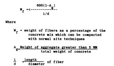 |
The
equation is designed to be concerned with only larger aggregate because sand and
small aggregate do not effect the workability of the concrete when using fibers
in concrete.
Field results indicate that steel fiber may best be added by weight in a range from 3 to 7%. Some field reports indicate fiber volume up to 400 pounds per cubic yard. This extreme volume fraction requires an admixture such as a superplasticizer. There is a host of research reports published relating to the positive effect of steel fibrillated concrete. Conversely, there are also draw backs to the use of this product. Steel fibers are bulky and require special care during the mixing cycle. It is also labor intensive to add steel fibers during the mixing cycle. If the fibers are not mixed properly, the concrete will form into balls. Referred to as balling, the coarse aggregates and steel fibers form large balls during the mixing cycle and produce an unacceptable final product.
Fiber
reinforced concrete (FRC) has been proven to be a crack arrester. FRC does
eliminate most micro cracking and assists in preventing plastic shrinkage.
Figure 1 graphically presents the process for stopping crack propagation.
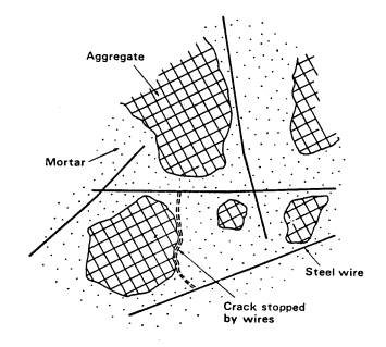 |
| Figure
1. Possible crack-stopping mechanism of steel fibers in concrete |
Also
pictured in this figure is the random orientation of the fibers as they lie
between the coarse and fine aggregates. This three dimensional strength
enhancement has proven very effective when comparing concrete tests in tension
and flexure.
There
is no doubt from field applications that steel fibers enhance the secondary
performance of concrete. With the use of many admixtures in concrete, care must
be taken to be sure the steel fibers are not affected by the admixture chemical
composition. One example is calcium chloride, which is a common admixture in
concrete. This salt base admixture attacks the steel fibers and causes corrosion
to form around the fibers. Edgington
[1973] has presented evidence that over a period of time, these fibers fail
structurally. As cracks appear in the concrete with age, moisture works into
these cracks. Salt erosion from highways or salt water are just a few examples.
Rust bleeding in architectural concrete is another application where damage must
be considered.
Polypropylene
fibers
Polypropylene
fibers (PPF) are utilized as a secondary reinforcement and are manufactured in
the isotactic configuration. They are extruded through a flat die and then slit
into tape form. The tape is next monoaxially stretched; this process is referred
to as "draw ratio." The draw ratio is a measure of the extension which
is applied to the fiber during fabrication, and draw ratios of about 8 (eight
times its original length) are common for polypropylene film. A molecular
orientation results from the stretching process and the resul is high tensile
strength. It may be noted, PPF is at its strongest state when placed in concrete
with tension or flexure as the primary design criteria.
The
raw material, polypropylene, derived from the monomeric C2 H6, is a pure
hydrocarbon. According to Zonsvield [1976], its mode of polymerization, its
highly molecular weight, and the way it is processed into fibers combine to give
PPF many useful properties.
PPF
has a sterically regular atomic arrangement in the polymer molecule with high
crystallinity. Its regular structure gives it the name isotactic polypropylene.
The material has a high melting point of 165 degrees C and has the ability to
withstand temperatures over 100 degrees C for short periods of time. This
temperature durability is important as secondary reinforcing material in
concrete. Polypropylene is chemically inert, which makes the fibers resistant to
most chemicals. If the concrete is exposed to aggressive chemicals, the cement
will be the first material to deteriorate.
Since
PPF has a hydrophobic surface, no additional water is needed in the concrete
mix. Because of this slick surface there is less chance for balling during the
mixing process as compared to steel fibers. Stated in textile terms, its
capabilities are 5g/denier, which is equivalent to 400 MN/m squared. Zonveld
[1976] goes on to state that this orientation leaves the film weak in the
lateral direction. This opening allows for the wet cement matrix to wrap around
the fibers during mixing, which in turn forms a mechanical bonding with the
concrete matrix.
PPF
has an advantage of being light in weight. Major North American PPF suppliers
specify its use at approximately one and a half pounds per cubic yard or about
.01% by volume per cubic yard of This is about 1.5 pounds of fiber per cubic
yard of concrete. Generally steel fibers will be added at 100 pounds per cubic
yard of concrete.
There
is no special mixing requirement necessary for PPF when mixed in the traditional
over-the-road concrete nixing truck. Forte Corporation (one major supplier),
specifies that PPF can be added at the batch plant or on-the-job site prior to
the placing of the concrete in its forms. One major concrete supplier in the
Midwest reported that adding the polypropylene fibers with the coarse aggregates
caused the fibers to open up sooner and resulted in a more homogeneous fiber
distribution. This firm also claimed that this extra step eliminated all balling
problems which resulted in delivery of a consistent high quality concrete for
contractors.
Just
as every material has useful applications, when utilized in a large variety of
settings, shortcomings do exist with polypropylene fibers. Even though PPF has a
high melting temperature compared to other polymers, it does not withstand heat
from fires in structures. When exposed to extremely high temperatures, which is
common in fires, PPF vaporizes and leaves a void in the concrete equal to the
volume of the original PPf in the mixture. This void left after a fire also
creates a porosity condition in the concrete which can not be corrected.
Since
PPF has a low modulus of elasticity, a high strain rate occurs before multiple
cracking appears. When compared to steel, which has higher modulus of
elasticity, PPF does not react in the same manner as steel. Between steel and
concrete, there is a close coefficient of expansion and contraction. Once a
crack occurs in concrete, the steel reinforcing assumes the total load for the
concrete mass. This creates a safety net, so to speak. PPF and concrete react
very differently. Because of its low modulus of elasticity, the polypropylene
fibers, directly assume the load until pullout occurs along the surface of the
fibers. At this point, known as the modulus of rupture (NOR), ultimate failure
occurs. In some testing, NOR in PPF is higher than in secondary steel
reinforcing. It should be recognized that there is a larger coefficient of
expansion and contraction between PPF and concrete than there is between steel
and concrete. This accounts for some of the differences in the behavior of this
material.
In
Figure 2 is a drawing which depicts the classification of fiber arrangements. As
can be viewed in specimen 1D, the fibers are aligned in a single plane, are
parallel to the longest side, and are centered in the object. A matting
arrangement is presented in specimen 2D. This is a newer configuration of PPF,
which has been recently field tested. In the cube marked 3D, or three
dimensional, is a specimen which shows how PPF is mixed throughout the concrete
matrix. When random fibers are mixed throughout the concrete, a three
directional reinforcing matrix develops. It should be understood that steel
fibers are linear in this three directional reinforcing. Polypropylene fibers,
being flexible, will wrap themselves around the coarse aggregates in a some what
different configuration.
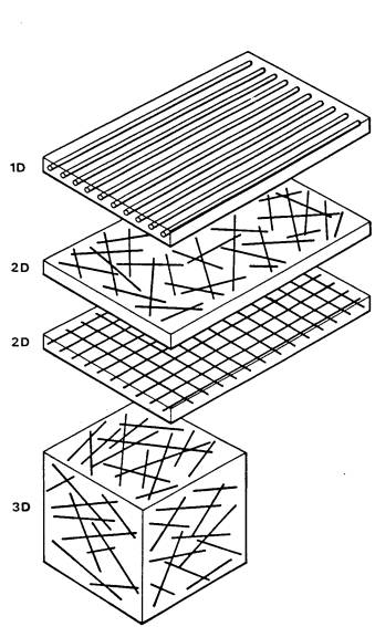 |
| Figure
2. Classification of fiber arrangements |
Chemical
admixtures
The
two chemical admixtures chosen for investigation in this study were experimental
additives. The process used to introduce these admixtures into the concrete was
also an experimental procedure. The first chemical admixture tested was oleic
acid. This is a natural chemical which is obtained by the hydrolysis of
vegetable fats, primarily from olive oil. It is separated from the olive oil by
the double fractionation urea aducts process. The chemical makeup is C 76.54%, H
12.13%, and 0 11.33%. Because this chemical is an experimental admixture the
performance of this chemical will be explained in detail the discussion section.
Basic-H
is a commercially produced solution supplied at full strength as a 28% water
solution base. The chemical is a nonionic surfactant of linear alcohol
alkoxylates. The manufacturer specifies that this agent when used as an
admixture will improve the strength of the concrete.
EXPERIMENTAL
DESIGN AND ANALYSIS
The
results reported in this paper were selected from two separate investigations.
One covers results from the chemical admixture composite group and the second
reports results of composites in relationship to secondary fiber reinforcement
only. The experimental designs for both projects are the same. The testing
procedures that both investigations followed conformed to standard concrete
practices of The American Society for Tests and Measurements (ASTM) and the
American Concrete Institute (ACI).
Both
experiments are factorial designs. The cast specimens were mechanically tested
and the data was evaluated using the statistical analytical system. Each project
was designed to compare samples from the control group with samples in the
treatment group. All groups are fully randomized, replicated and verifiable
statistically.
Chemical
treatment investigation
As
reported earlier the two chemicals tested in this project were oleic acid and
Basic-H. The process chosen to inject the chemical admixture into the concrete
was to coat the polypropylene fiber surfaces with the admixture. Each set of
fiber groups were allowed to soak in a designed chemical bath for 10 minutes and
then allowed to air dry. At a later time the surface treated PPF were introduced
into the concrete while it was being mixed.
As
can be seen on Figure 3, there is a control group concrete with no fiber
reinforcement. The three treatment groups are listed as plain polypropylene
fibers (no chemical admixture surface treatment) polypropylene fibers with oleic
acid on the surface and polypropylene fibers with Basic-H on the surface.
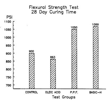 |
| Figure
3. Flexural test comparison |
Results
from the flexure test indicate the Basic-H admixture treatment group achieved
the highest strength values after 28 days of curing time. These results are the
averages of 14 test beams in each group with a total of 56 beams overall. All
flexure tests were conducted following ASTM procedures conforming to C-78
specifications.
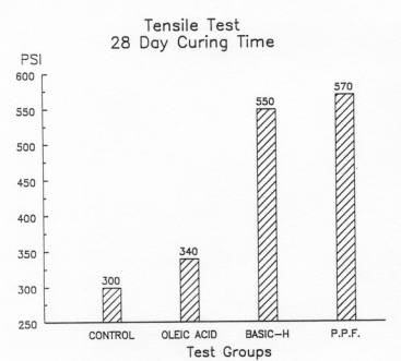
Presented
in Figure 4, are the tensile test results after 28 days curing period. In this
test there were a total of 6 samples tested in each group. In all testing, each
group was split and replicated to improve the reliability of the research and
statistical results.
 |
|
Figure
4. Tensile test comparison |
Composite
fiber investigation
This
second part of the investigation reports concrete enhancement through the use of
composite fiber reinforcement, since steel and polypropylene fibers have been
tested extensively individually.
Reported
in Figure 5 are the results of this composite. This test was conducted with a
total of 24 flexural beams. The averages are reported on this bar chart. To date
these two materials have been tested with commercial admixtures. Dr. Naamen at
Michigan State and other researchers have reported their findings.
PRESENTATION
OF DATA
The
mechanical testing results of the concrete specimens are listed on the figures.
The flexure test was conducted with two measures for each sample. A direct
measure was calculated for the elastic limit of the beam at center point, more
commonly referred to as "E". The second measurement calculated was the
modulus of rupture (MOR). The modulus of rupture is calculated from the
relationship
 |
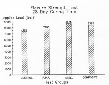 |
| Figure
5. Composite fiber flexure test |
The
modulus of rupture of the strongest treatment group was the Basic-H enhanced
fiber treatment. Conversely the weakest set was the oleic acid group. The
composite fiber tensile test revealed the steel fiber group reached the highest
applied load at first crack failure of the concrete. The tensile test was
conducted utilizing the tensile briquette technique. Since the cross sectional
area of each specimen is one square inch, a direct conversion is calculated from
the applied load.
DISCUSSION
Mechanical
testing of concrete will generate data to analyze and reveal a statistical
inference from these results. There are other additional methods of analysis to
assist in explaining these test results. One tool available is the use of
nondestructive evaluation. The scanning electron microscope (SEM) is a powerful
tool to assist in materials research. A brief summary of the scanning electron
microscope findings is included to help explain the results of the plain
concrete, concrete with plain polypropylene, and PPF treated with oleic acid or
Basic-H. As can be viewed in Figure 4, there is a statistical significance
between plain concrete and PPF with Basic-H.
Chemical
fiber treatment
The
data reported here are the first results of several investigations using oleic
acid and Basic-H as an admixture. The reader can see that the findings presented
in Figures three and four do not clearly indicate which chemical treatment had
the highest and consistent performance enhancement in the concrete. One of the
goals at the beginning of this research was an attempt to improve the
interfacial bond between the polypropylene fiber and concrete matrix.
The
oleic acid SEM micrographs revealed a crystalline matrix at the fiber interface.
There was no doubt that an interfacial chemical enhancement was achieved. Why
had this bonding not improved the overall ultimate strength of the concrete? Not
until careful examination of the SEM photos was it discovered that the
crystalline growth had a lower elastic modulus than the polypropylene fibers.
What occurred was a failure at the fiber interface or a sleeve slipping action.
Therefore lower ultimate strengths were recorded in the oleic acid samples. This
explains the poor performance of these fibers in tension. An extensive review of
this phenomenon can be viewed in work by Lovata and Fahmy [1987].
The
results of Basic-H as an a full scale laboratory admixture are not conclusive.
The test results from several investigations indicate potential use of this
chemical as an early high strength concrete enhancer. It can be reported that
long term testing (45 day tests) of Basic-H had not revealed a statistical
significant improvement in the concretes ultimate strength.
Composite
fiber treatment
The
fiber flexure test reveals the averages at first failure in the concrete. As
observed in Figure 5, there is a modest gain in the performance of the concrete
with polypropylene as a secondary reinforcement. From this one observation (at
first crack observation) it appears the steel fiber reinforced concrete has the
highest potential for ultimate strength. It should be understood that in the
stress strain relationship where concrete is subjected to tension or flexure the
concrete will crack. What happens after that initial failure is referred to as
the post peak loading condition.
The
same concrete failure occurs whether it is in a laboratory situation or field
application. Once the concrete cracks, the primary reinforcement, steel re-bars
and secondary reinforcement, fibers assume the load for the structure. Therefore
the long term performance of the concrete or post fracture condition must be
considered. Shah et. al.[1988] has reported findings regarding this condition.
The performance results from the composite fiber concrete reveal a change in the
elastic limit "E" value of the concrete. After the first crack was
recorded in the composite concrete, the post-peak loading curve indicated a
change in performance compared to the steel fiber reinforced concrete. The
composite concrete sustained (by time) a much higher load curve.
Once
the composite post-peak loading situation is fully investigated and reported, it
will no doubt will have a long term effect on the future design of composite
fiber reinforced concrete.
CONCLUSION
This
investigation verifies that experimental chemicals and composite fibers can
improve the overall secondary reinforcement performance of the concrete matrix.
ACKNOWLEDGMENT
This
research was sponsored in part by Forta Fiber Corporation, Grove City, PA.
REFERENCES
|