(pressing HOME will start a new search)
![]()
![]()
- ASC Proceedings of the 24th Annual Conference
- California Polytechnic State University - San Luis Obispo, California
- April 1988 pp 10-19
|
(pressing HOME will start a new search)
|
|
COMPUTER-AIDED DESIGN AND DRAFTING AS A CONSTRUCTION MANAGEMENT TOOL
|
Robert
R. Weiland |
|
Computer-Aided
Design and Drafting (CADD) systems are rapidly replacing drafting boards
in many architectural and engineer�ing firms. Unfortunately, the
extensive information generated by CADD systems is seldom fully
utilized. Information stored in drawing files has the potential to
provide a data base for management of the entire construction process. Producing a
quantity take-off from a drawing-file data base is one example of the
contribution CADD systems offer construction managers. This study
investigates using CADD to create a material take-off for volumetric
concrete quantities. Other management uses for CADD data are also
suggested. The potential
of CADD as a construction management tool is especially important to
university-level educators. The argument has been advanced that
construction management students need not be familiar with CADD systems
because "graduates will not be draftsmen". Using CADD-generated
drawing files as a project management tool may soon change that
perception. KEY WORDS:
CADD, TAKE-OFF ESTIMATING INTEGRATION DATA BASE |
INTRODUCTION
In
today's highly competitive construction environment, successful project
management requires the use of increasingly sophisticated tools. Computerized
estimating, scheduling and cost control programs are becoming industry standards
for project management. New products and technologies are continually being
developed to assist the construction manager.
Estimating
is one construction management task to which new technologies are being applied.
Computer programs have been developed to assist the estimator in quantifying and
pricing the materials. These programs require the estimator to interpret
information contained in the plans and specifications. When the estimator has
determined the architect's intentions, the project data must be entered into the
computer. Data entry can be a time consuming and expensive oper�ation. In
addition, the data entry process is subject to misinterpretation and error.
A
procedure is needed to enable automatic input of the architect's intentions for
estimating analysis., Linking the design process with the estimating process
should significantly reduce the chance for omission and error by the estimating
team.
Significance of the Problem
The
Importance of the Quantity Take-Off
Preparation
of the quantity take-off is a key function in the estimating process.
"Perhaps the most basic as well as the most important aspect of the
contractor's estimating and bid functions is the taking off of work quantities
from the two-dimensional drawings representing a project," (Adrian, 1982).
Clough wrote:
"A
major cost incurred in preparing an estimate is the procedure of organizing and
counting the materials and equipment required to complete the work. This
procedure, known as the quantity take-off, produces a complete listing of the
materials and items of work that will be required. Using these work quantities
as a base, the contractor computes the costs of the materials, labor, equipment,
subcontractors, taxes, insur�ance, overhead and contract bond. The sum total of
these individual items of cost constitutes the anticipated overall cost of the
construction." (Clough, 1981)
Preparing
the quantity take-off with conventional procedures can be a time-consuming and
costly process. With conventional practices, an architect prepares drawings and
specifications which define a construction project. These construction documents
are typically provided to several bidding contractors who must interpret them.
Each contractor must independently determine the quantity of materials, labor
and equipment required for construction of the facility. As Spradlin has noted,
this practice often results in confusion.
"If
20 estimators or contractors were furnished the same set of plans and
specifications and told to prepare an estimate of cost from them so that the
different methods might be compared, it is safe to assume there would be not
more than two estimates in the entire twenty that had been prepared on the same
basis or from the same units." (Spradlin, 1982)
A
tool is needed which is capable of providing all bidding contractors with an
identical quantity take-off. This will insure that all contractors compete on an
equal level. The low bid will result from a contractor's expertise at finishing
the job, not an overlooked component of work. The redundant costs incurred when
several competing firms prepare quantity take-offs for the same project will be
avoided. This will lower the overhead expense of all contractors and should
eventually be reflected in lower construction costs.
Computer-Aided Design and Drafting as a Take-Off Tool
Computer-aided
design and drafting (CADD) may be the tool which is capable of providing the
uniform quantity take-offs needed by the industry. An age-old adage states,
"A picture is worth a thousand words". In simple eloquence this phrase
captures the power of CADD.
Individuals
who use CADD systems are familiar with the benefits of producing graphic images
with computers. However, there is also a great deal of useful non-graphics
information contained in CADD drawings, (Breslin, 1987). For example, a line on
a computer screen representing a
wall
to the draftsman is actually stored in great detail in the drawing file. A list of the typical information stored for a
single line includes:
|
The
very specific and detailed information stored in CADD drawing files offers
considerable potential to the construction estimator. If this information can be
used to provide quantity take-offs, more accurate and detailed estimates may be
attainable. Instead of manually measuring the drawings for quantities, the CADD
system could provide the required infor�mation. Transferring information
directly from the CADD drawings would insure that the architect's intentions for
material usage will be clearly relayed to the estimating team. Clear
communication between the designer and the estimator will eliminate uncertainty,
confusion and delays from the construction process.
"CADD-generated
drawings offer incred�ible potential at integrating the flow of information
within the construction industry. With CADD systems, archi�tects are able to
create drawings and drawing files that contain geometry and attribute
information. This quanti�tative information can be passed to the estimating
system." (Robinson, 1986)
Purpose Statement
The
purpose of this study was to investigate the use of Computer-Aided Design and
Drafting as an estimating tool. Drawing files prepared with a
microcomputer-based CADD system served as the data base for quantity take-off
preparation.
Delimitations
and Limitations
|
PROCEDURES
This
study investigated the use of CADD-generated drawing files to produce quantity
take-offs. Research was delimited to producing concrete quantity takeoffs for a
simple foundation system. The study proceeded in the following steps:
Step 1
Creation of the Foundation Master Drawing
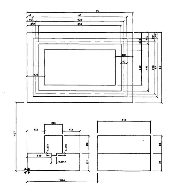
A
master drawing for a simple foundation system was created using the Synthesis
and AutoCAD programs (Figure 1, "Foundation Master Drawing"). The
Synthesis Master Drawing file defines a standard shape with variable dimensions.
These variable dimensions are easily recognized by the "$" preceding
the variable number. This variable-labeling convention is required by the
Synthesis program.
The
variables created in the master drawing can be defined, or
"rectified", to create infinite variations of the drawing. This allows
a designer to create one drawing file for each standard shape. For example, the
foundation system shown in Figure 1 can be altered to represent any other
rectangular foundation system.
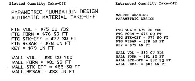
The
Foundation Master Drawing contains a simplified quantity take-off. This section
of the drawing, labeled "AUTOMATIC QUANTITY TAKE-OFF", was updated
auto�matically to reflect dimensional changes of the master drawing variables.
The "AUTOMATIC QUANTITY TAKE-OFF" is part of the drawing file and is
stored on the layer named "Quantities". For clarity, the
"Quantities" layer was turned off when the foundation plan was
plotted. This layer was plotted separately and is presented in Table 1,
"Foundation Master Drawing, Quantities Layer".
Nine
items were automatically calculated when the Foundation Master Drawing file was
updated. These quantities were:
|
The quantity take-off is reported twice in Table 1. The first take off was plotted directly from the drawing file. The second quantity take-off was created by exporting information from the drawing file to a word processing program. The take-off data was then printed with a daisy wheel printer.
Step 2
Development of the Foundation Master Spec Sheet
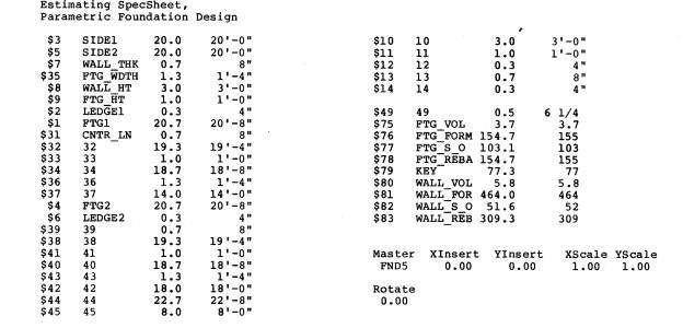
The
SpecSheet which defines the master drawing variables is presented in Table 2,
"Foundation Master SpecSheet". The SpecSheet was completed during a
para�metric design session provided by the Synthesis software. The parametric
design session prompts the user for needed input and creates an updated
SpecSheet and drawing file.
The
Synthesis SpecSheet provides many functions normally found only in spread�sheet
programs. For example, formulas may be entered in SpecSheet cells. These
formulas are used to calculate dimension variables specified in the master
drawing. The Foundation Master SpecSheet requires the user to supply values for six
of the thirty-nine variables shown in Figure 1. (The thirty-nine variables
are listed in column one of Table 2.) The remaining thirty-three variables are
calculated by formulas contained in the SpecSheet.
Step 3
Definition of Foundation Master Drawing Variables
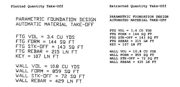
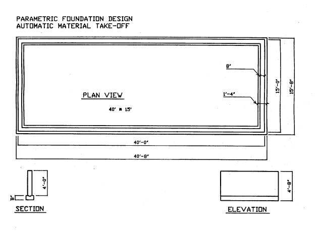
The
dimension variables contained in Figure 1 were defined using the parametric
design feature of the Synthesis program. Figure 2, "Rectified Foundation
Drawing", presents the revised foundation drawing. The quantity take-off
for the revised foundation drawing is presented in Table 3, "Rectified Foun�dation
Drawing, Quantities Layer". The quantity take-off for the foundation
drawing revision is presented in plotted format and in standard type.
Step 4
Presentation of Data
The
results of the study were plotted using a Hewlett/Packard 7475-A pen plotter or
exported to a word processing program for text editing.
SUMMARY
This
study was conducted to determine if the data stored in a microCADD drawing file
could be used to generate a quantity take-off. Research was performed using
AutoCAD 2.5 and Synthesis 2.5 software. A master drawing and accompanying
SpecSheet were created for a foundation system. The variables shown on the
master drawing were then defined to create a drawing and quantity take-off.
Using
the procedures previously described, a quantity take-off was prepared for a
simple concrete foundation system. This was accomplished by direct manipulation
of the drawing data. Repetitive data entry (once to create a drawing and again
to produce a quantity take-off) was completely eliminated. The quantity data was
then exported to another program (work processing) to explore the flexibility of
the system. Exporting data was easily achieved.
Procedure Analysis
The System
The
Synthesis software was easy to learn and required little train�ing. This should
allow rapid system implementation. However, the user must be thoroughly familiar
with AutoCAD software in order to use the Synthesis program. When creating the
master drawing, the Synthesis software was almost transparent to the user. The
basic AutoCAD structure and commands were not changed and could be invoked from
within the Synthesis program. A user that is well acquainted with the AutoCAD
software should have little difficulty adapting to the Synthesis program.
The
Synthesis master SpecSheet was also relatively simple to learn. The SpecSheet
performed much like most popular spreadsheet programs. However, the SpecSheet
does impose certain restrictions on the user. For example:
|
After
the master SpecSheet was created and tested, revision of the drawing and
subsequent creation of an updated quantity take-off was very simple. The screen
prompts were answered and the program did the rest. The culmination of this
parametric design session was the creation of a functional version of the
foundation drawing and an automatic update of the quantity take-off.
Foundation Master Drawing Analysis
Creating
and rectifying the Master Foundation Drawing revealed some important factors
about applying the Synthesis software to the construction environment. The most
important discovery was the degree of complexity required for the master drawing
layout. The complexity required by the master drawing is apparent in
Figure 1. The Synthesis program requires that all variables be referenced to
a common point. This results in a master drawing that is complex and time
consuming to create.
The
simplistic foundation system chosen for this study would be the exception in
actual practice. A more complicated foundation system would be typical. Using
the Synthesis/AutoCAD programs to manage a complex construction project would be
cumbersome. However, after the Master drawing was created, rectifying the
foundation drawing was simple to perform. The problems encountrered in design of
the drawing would seem to over-ride this utility.
CONCLUSIONS
The
research has conclusively shown that volumetric quantity take-offs can be
produced from the data stored in drawing files prepared with a microCADD system.
Furthermore, the software chosen for this study provided complete automation of
the process through parametric design. This parametric design function allowed
the user to make changes to pre-defined variables of the master drawing. These
design changes were then rapidly reflected in both the drawing and the material
takeoff.
An
added utility of the system was the ability to easily export data to other
software. The updated bill of materials was exported to a word processing
package for reporting. It should be equally
simple
to export the data to spreadsheet, scheduling and other software. Linking the
data stored in the drawing files to other software may provide integration of
the many construction management functions.
This
study has effectively demonstrated that the two-dimensional environment of many
microCADD software packages is not a significant barrier to producing volumetric
(three-dimensional) quantity take�offs. The ability to include all views (plan,
elevation, section and detail) in one drawing, in effect, creates a three
dimensional data base. This practice proved very functional for this study.
RECOMMENDATIONS
Construction Applications for AutoCAD/Synthesis Programs
The
results of this study prove that data stored in AutoCAD files can be used to
prepare accurate and detailed material take-offs. However, due to the
considerable effort required to produce these take-offs, the practical
application of the Synthesis program to the construction environment must be
questioned.
The
Synthesis master drawing and master SpecSheet should be created when a project
drawing is first produced. While it is possible to alter an existing drawing to
conform to the Synthesis standards, this is not an easy process and would likely
prove to be uneconomical. Preparing the Synthesis master drawing and SpecSheet
during the design stage would become the responsibility of the architect. This
is an added responsibility the architectural community is not likely to accept.
A
construction firm involved in design work may want to consider using the
Synthesis and AutoCAD software combination. The parametric design feature
provided by the Synthesis program can produce any variation of the original
master drawing. (Provided all variables have been anticipated and defined). If
master drawings and SpecSheets were created for typical building systems,
considerable time and effort might be saved when creating variations of these
systems.
The
ability to provide accurate and detailed quantity take-offs for concrete, as
demonstrated by this study, shows great potential for construction management.
Applying the techniques outlined in this study to other quantity take-off
problems should be feasible. The problems encountered in producing the quantity
take-off indicate that further software development is needed. Software should
allow quantity
take-offs
to be prepared without requiring the intensive master drawing and SpecSheet
design. If this modification were accomplished, the Synthesis/AutoCAD
combination could prove to be an invaluable tool to the construction estimator.
CADD
Applications to Other Management Tasks
Further
study on microCADD applications for the construction environ�ment are both
needed and justified. The potential advantages to be gained by tapping the vast
information stored in a typical drawing file are many. This approach should
provide increased speed and accuracy in processing the voluminous project
information. In addition, using CADD files as a data base for project management
may provide the integration of information which is needed to effectively manage
a construction project. Further study exploring the application of a CADD data
base to cost control, scheduling and estimating functions is needed.
CADD-Based Scheduling and Cost Control
The
scheduling requirements for many construction projects are becoming increasingly
rigorous. As owners become more sophisticated, they are requiring construction
management personnel to provide comprehensive construction schedules.
Unfortunately, many detailed job schedules wind up as wall paper for the
construction shack and are not really used to control the job.
Obsolescence
is a major factor in the lack of schedule use. A detailed schedule prepared at
the beginning of the project will often become outdated within weeks. Schedules
must be continually revised to provide useful information. Updating a schedule
with conventional techniques often requires greater effort than the perceived
benefits. A mechanism is needed to automatically link the scheduling process
with project revisions.
Exporting
data from CADD-prepared drawing revisions to the scheduling program may provide
such a link. As revised drawings are prepared, the data can be exported to
scheduling programs. Revised schedules can then be prepared with a minimum
expenditure of effort. This would eliminate much of the effort associated with
schedule revision.
Another
common problem facing construction managers is the lack of an integrated
approach to cost control. The construc�tion schedule must be combined with the
estimate to produce an effective cost control system. Scheduling, estimating and
cost control are therefore inseparably linked by function. Costs cannot be
controlled without effective scheduling and estimating.
A
CADD-based management approach may provide the means to effectively integrate
estimating, scheduling and cost control. Integration of these functions would
provide cohesive control of project cost and duration. Using the construction
drawings as a data base for the other management functions could insure a smooth
flow of information between all management groups.
Educator's Role
Microcomputer-based
CADD systems offer incredible potential to the construction industry. Linking
the design process with estimating, scheduling and cost control will improve the
entire construction process. However, further study on microCADD applications
are needed.
Educators
have traditionally provided leadership in exploring the development and
application of new technologies. Using CADD technology for construction
management should be no exception. The exhaustive project information stored in
CADD drawing files represents an untapped resource for construction management.
The
rapid expansion of CADD technologies in recent years forecasts increased
reliance of this technology in the future. If educators are to maintain their
pro�active position in technology development, CADD research and training are
neces�sities.
REFERENCES
|
DEFINITIONS
|
|
TABLE
1. FOUNDATION MASTER DRAWING, QUANTITIES LAYER |
|
|
|
TABLE 2. FOUNDATION
MASTER SPECSHEET |
|
|
|
TABLE 3. RECTIFIED FOUNDATION DRAWING, QUANTITIES LAYER |
|
|
|
|
|
Figure
1.
Foundation Master Drawing |
|
|
|
Figure
2.
Rectified Foundation Drawing |