Back Home Next
ASC Proceedings of the 41st Annual Conference
University of Cincinnati - Cincinnati, Ohio
April 6 - 9, 2005         
 
Comparing Two Construction Methods on the Steel Bridges Economy
 
Reza Farimani, EI and
Atorod Azizinamini, Ph.D., PE
University of Nebraska
Lincoln, Nebraska


Nick Lampe, EI
HDR Engineering, Inc.
Omaha, Nebraska
 
 
Market analyses of materials used in bridges with short to medium spans indicate a decline in the use of steel girders over the last two decades. A new construction technique was developed to enhance the competitiveness of the steel girder bridges in the short to medium span length ranges. In the new method, the beams are erected as simple spans under the construction loads. In this case the field splices are eliminated. The continuity of girders for the traffic loads will be achieved by the concrete diaphragm detailing over the pier. The cost of two bridges being constructed using the new design were compared to the cost of the conventional steel bridge. The comparison revealed that the cost of superstructure decreases with new design and labor costs involved in fabrication and erection decrease. The implementation of the new concept improves the site workers safety and requires less installation equipment.
 
Key Words: Steel Bridge, Construction Method, Erection, Field Splice, Cost Estimate
 
 
Introduction
 
The four principal bridge materials, which according to the Federal Highway Administration (FHWA, 2003) represent 99 percent of the bridges built in the United States since 1982, are prestressed concrete, steel, timber, and reinforced concrete. Based on the study done by Smith et. al. (1995) the initial cost of each alternative and long-term maintenance costs are the most influential criteria in choosing bridge materials.
 
The construction market sectors such as steel fabricators, concrete industries, or timber companies are promoting the application of their desired material. The competitiveness of each material in the bridge market is crucial for the manufacturers. The lower initial cost and maintenance costs are two important factors for the bridge decision-makers to consider when selecting the primary bridge material. Another issue that is important for the engineers in selection of material is the duration of the project. The shorter construction time allows the bridge to be opened sooner and returns more profit for the public or private owner. In the latter half of the twentieth century concrete bridges, especially prestressed concrete became popular because they were economical and durable. One consequence of the rise in popularity of concrete bridges was decline in the use of steel bridges of short to medium spans. However, the major factors for the diminishing competitiveness of steel bridges in this span ranges are attributed to higher material and construction costs. The unit price of the steel girders and components are not controllable by the professionals involved in the design or construction of the bridges. However, construction costs can be reduced by employing innovative methods. The National Bridge Research Organization responded to this issue by developing a new concept following interviews with the steel bridge fabricators and contractors.
 
In the proposed concept, the expensive conventional details are eliminated in the design of bridge girders. The erection costs of the steel girders designed as simple spans are cut considerably when the details typical of the conventional steel bridge are eliminated. In the following sections the need for the new method, its benefits, and its performance in two bridges recently built are addressed.
 
 
Bridge Materials Market Analysis
 
An 11-year overview of National Bridge Inventory (FHWA, 2003) data obtained from the Federal Highway Administration (FHWA) for fifty states is shown in Figure 1. The data was separated into categories based on the material of bridge construction. It is seen that the number of steel and timber bridges constructed in this period are declining while the number of concrete and prestressed bridges are increasing. To identify trends in the use of bridge materials, a detailed market analysis was carried out by Lampe (2001) in the mid-west region of the United States. Based on these trends identified through the market analysis for a time period from 1911 through 1998 the primary conclusions were as follows:
 
  1. The use of timber as a bridge construction material, although basically limited to lower span lengths, has significantly decreased over the time period examined.
  2. In most states studied, reinforced concrete has remained a fairly consistent choice for span lengths of 50 ft or less.
  3. Prestressed concrete construction captured a large share of the market in the 60 ft – 100 ft span ranges in the 1960’s and 1970’s. The current trends indicate that prestressed concrete has extended its presence as a construction material choice across all span lengths. In the last two decades, steel bridge construction in all span lengths has either remained steady or decreased in number.


In the short span ranges (80 - 110 ft), prestressed concrete girder bridges have become the dominant bridge type.
 
The market analysis shows the steel girder bridges are less competitive in short to medium span bridges compared to the prestressed concrete types. The purpose of this research is to reduce cost of steel bridges in the span length range of approximately 80-150 ft.
 
 Figure1 : The number of bridges in the US based on the construction material
 
 
Conventional Versus New Method
 
The current design methodology for the multi-span steel bridges is to build continuous bridge girders to distribute applied loads more evenly between the spans. The steel girders are usually fabricated in the shop in several pieces due to handling limitations and then transported to the site for the assembly. The multi-span steel bridges are connected together at the site to make the continuous beams. The construction sequence consists of placing the middle segment and connecting the two end sections using a bolted or welded field splice. When using bolted splices, estimates for the average cost of material, installation and inspection of one bolt can be as high as $20.00. The location of field splices due to structural design considerations is preferred to be somewhere between piers rather than on the piers. This type of construction usually requires extra cranes or temporary shoring (see Figure 2) for erection with a possible interruption to traffic. The connection of two steel girders while hanging in the air can be hazardous for the steelworkers. Furthermore, the detailing and fabrication of splice holes requires extra inspection cost to avoid installation errors. In a series of discussions with designers, fabricators, and contractors, two factors were identified to be essential in improving the system:
 
bullet
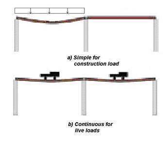
Elimination of field splices,
bulletSimplification of the type of details at the pier location.
 
Based on the developed new concept, designers specify steel girders in simple span configuration as shown in Figure3-a (girders sit simply on the abutments and piers). In the field the contractor fixes them with a partial concrete diaphragm at the pier. This technique greatly simplifies the formation of continuous girders, which would otherwise be bolted or welded together in the field by the contractor. After placing each girder on the bearing pads, the concrete of slab and remaining portion of the diaphragm is poured. The concrete deck, diaphragm and longitudinal reinforcing provide the continuity of two adjacent steel girders for the traffic loads and superimposed dead loads (Figure 3-b). The advantages of this method of construction were investigated in a parametric study (Lampe, 2001) and are as follows:
 
bulletThe need for expensive field splices are completely eliminated for spans of up to 150 ft (as controlled by transportation considerations).
bullet
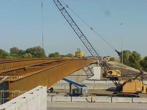
The contractor will need fewer cranes for installation. The need for less installation equipment allows smaller contractors to bid for jobs.
bulletA uniform cross section can be utilized for the entire span which reduces the fabrication effort.
bullet
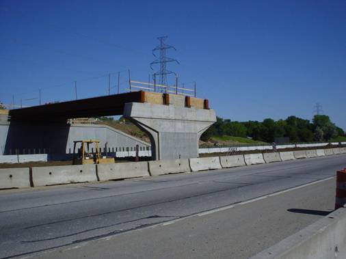
Girders can be placed over the support without significant interruption to the ongoing traffic.
bulletImproves safety of steel workers.
bulletThe placement of girders directly on the pier and abutment reduce the erection time.
bulletMinimal detailing of the steel beams.
bulletNo need for temporary shoring.
 
On the other hand, the proposed design increases the amount of steel required because of the simple span design. However, implementations of simpler details enhance the overall economy of the bridge. Traditionally, the cost of materials was more important in the estimation of the total cost of a project but, now the least labor generally results in least cost. Labor costs can be substantially reduced by using simpler details in the new method.
 
 Figure 2: The conventional erection method of steel girders
 
 
 Figure 3: The new method of construction of the steel bridges
 
Case Studies
 
To validate the economic advantages of the proposed concept, a parametric study was carried out. In this study, two steel bridges that have been recently constructed based on the new concept were selected. The design of the steel bridges superstructure follows AASHTO-LRFD Bridge Design Specification (2001) provisions. Both bridges were redesigned based on the conventional method and the new concept for comparison purposes.
 
Sprague Street Bridge
 
The Sprague Street Bridge over Interstate 680 is located in Omaha, Nebraska and was opened to traffic in August 2004. The bridge has two spans, each 97 ft long with 4 I-girder cross section. The clear roadway width is 32 ft, with a 7 ft pedestrian sidewalk on the south side of the bridge. Cast-in-place deck thickness is 7.5 in. with ½ in. integral wearing surface. 50 ksi weathering steel was used for fabrication of the rolled I-girder. The Sprague Street project was selected for two reasons first the 97 ft spans represent a common two-span bridge constructed in the US in the short span range and second, the project was recently designed and erected and would provide up-to-date information about the construction.
 
N-2 over I-80 Bridge
 
The N-2 Bridge was recently designed and constructed at Nebraska Highway 2 over Interstate 80. The Bridge structure consists of two 139 ft spans, and a 3-box girder cross section. The spacing between centerlines of the boxes is 16'-1-in. and supports a 46’-4-in. clear roadway and a pedestrian sidewalk. The cast-in-place deck thickness is 7.5 in. with ½ in. integral wearing surface. Exterior girder overhang is 4’-1-in. from the center of the exterior girder to the edge of deck. 50 ksi weathering steel was used for fabrication of the box girders. The bridge was built using the proposed construction method. The reason in selecting this bridge was to examine the new concept on the different cross sections and its practicality in the medium span length range.
 
Design Procedure and Results
 
The designs for the preceding bridges were carried out using two methods; first, as a continuous beam for dead, live and superimposed loads (conventional method) and second as two simple beams for dead load and continuous for live loads according to the new proposed concept, which was described earlier. A summary of the design results is given in Table 1. The variation of flanges thickness was limited to two thicknesses along the girder length to include the practical fabrication considerations. However the computed thickness is not market standard size. The web depth and thickness remained constant in both methods to satisfy the deflection requirements. In weight calculations the weights of stiffeners and cross frames were ignored since they are similar in both alternatives. The values in the table are presented as ratios in the form of demand/resistance. The flanges thickness was changed to obtain a demand to the strength ratio of section close to 1.00. The designs were optimized in terms of steel weight only. It is noticed that for each case the weight of designed steel girder based on the new technique is more than that of the conventional approach. For the box girder, new design results in 4 percent additional steel compared to the conventional method. This percentage is approximately 3 percent for the I-girder.
 
Table 1
 The girders’ properties
 
Box Girder
I-Girder
 
Conventional Method
New Method
 
Conventional Method
New Method
Top Flange Sizes (in)
(16x0.64) & (16x1.3)
(16x0.7) & (16x0.8)
 
(15.8x0.5) & (15.8x2.6)
Web Sizes (in)
(50x0.375)
(50x0.375)
 
(36.56x0.75)
(36.56x0.75)
Bottom Flange Sizes (in)
(72x0.64) & (72x1.3)
(72x0.7) & (72x0.8)
 
(15.8x0.5) & (15.8x2.6)
Demand/Strength Ratio
1.00
1.00
 
1.00
1.00
Weight of 1 Girder (kips)
52.47
54.63
 
21.46
22.07
Weight Increase Percentage
4.13%
 
2.82%


Cost-Benefit Analysis
 
In the previous section it was noticed that the new design resulted in a slight increase in the weight of the steel girder, but eliminating field splices resulted in a less costly installation. In addition to the weight of steel and field splices, the other parameters also change the cost of bridge construction in each approach, however the major variables are the weight of the steel girder and the cost of the field splices.
 
The cost of a steel girder consists of material, labor, and equipment costs. The average bid unit price of fabrication and erection of each steel girder is listed in Table 2. The unit price is based on the assumption that the girders have been fabricated using the conventional method. Since the weight of the girders designed following the new technique is greater than the conventional method, the total price of each steel girder is also greater. The increase in the cost of the materials by utilizing the new concept is $923 for one I-girder and $2,380 for one box girder. The cost differences for 4 I-girders and 3 box girders due to the weight of steel are given in the row c of Table 2 for each bridge. It is noted that this cost comparison is based on the unit price of a steel girders designed and constructed using the conventional method.
 
The cost of fabrication and installation of each field splice needs to be estimated in order to determine the extra cost of each girder based on the conventional method and compared to the new concept. The cost of fabrication and erection of one field splice for each girder consists of the cost of bolts, holes, plates, an extra crane, steel workers for installation, and inspection. The unit price and required time for each item was obtained from RS Means Open Shop Building Construction Cost Data (2003). A 55 percent surplus was added to the total cost of material, equipment, and labor to consider the overhead, profit, and indirect costs of the contractor. The typical field splice designed for the I-girder bridge is shown in Figure 4. The fabrication and erection of each splice costs about $2,000 for each I-girder. It is shown that the additional field splice adds approximately 13 percent to the total cost of each steel I-girder, while employing the new technique, increases the steel material cost only by 6 percent. Therefore, there is 7 percent savings by using the new method of construction.
 
Another splice detail was designed for the box girder and the cost was estimated by the same method as described for the I-girder. The cost of each field splice is about $6400, which is 11 percent of the total cost of a box girder. The increase in cost due to extra weight is about 4 percent. Therefore, by the elimination of each splice by using the new method the contractor would save up to 7 percent for each designed box girder. In Table 2, the cost savings due to elimination of all the splices are given in row d. Finally, the net saving in cost of each bridge is determined by subtracting these costs from the additional steel weight costs (d – c), which is listed in row e of Table 2.
 
The extra time for the fabrication and erection of each splice was evaluated based on a crew consisting of two steel workers for fabrication and installation and one crane operator and one inspector. The total estimated time for the field splices of the I-girders is about 10 hours. This will extend the project time about two days, since the fabrication and erection of a steel girder is usually on the critical path of the project schedule. The time estimation for the box girder indicates that employing field splices can extend the project time for more than 4 days. The estimated time saving by using the new method is given in row f of Table 2 for each bridge.
 
Table 2 
Cost and time comparison between two methods of construction 
 
Box Girder
 
I-girder
 
Conventional
New
 
Conventional
New
a) Weathering steel unit price (per lb)
$1.1
$1.1
 
$0.75
$0.75
b) Total Price of girders based on the weight
$173,136
$180,279
 
$62,508
$66,204
c) Cost difference based on the weight
$7,143
 
$3,696
d) Cost saving due to elimination of splices
$19,200
 
$8,000
e) Net cost saving by using new method
$12,057
 
$4,304
f) Total time saving of the projects
4 days
 
2 days
 
 
 Figure 4: I-girder field splice detail used in calculations
 
 
New Concept in Practice
 
The Sprague Street over I-680 and the N-2 over I-80 Bridges were constructed based on the new technique in Nebraska in 2003 and 2004, respectively. The I-girder bridge was made of a rolled shape section with a uniform section across the length and thus did not need any change in cross section. The only additional detail added was the end bearing plates which were welded to both ends of the girder in shop. The cross section of the box girder was also uniform across the span length; therefore the plate waste was minimized.  The additional end bearing plates were welded to the ends to improve the stability of the box girder and continuity of the bridge system after pouring the concrete.
 
The girders of the first span of Sprague St. Bridge were set independently (see Figure 5) without erecting the second span girder, therefore the traffic under the second span did not need to be interrupted. The independency of the girders setting in two spans is not possible with the current method of practice since the girders must be continuous over the pier (Figure 2). The girders of first span were erected at night in order to minimize disruption to traffic, as Interstate 680 below had to be closed during that time. The cost for in place erected steel for the Sprague Street Bridge is approximately $0.52/lb. This compares to rule-of-thumb value of engineering estimates of $0.75/lb for erected rolled steel bridges having conventional bolted field splices (Azizinamini and Vander Veen, 2004).  The duration of the project was about 6 calendar months. The elimination of field splice could have been shortened the project schedule about one day which is approximately 1 percent of total project duration.
 
The erection of the 139 ft box girder was carried out by two crawler cranes (Figure 6) without any temporary shoring.  The placement of each girder from the semi-trailer on the abutment and pier took about 20 minutes. As it was pointed out earlier the installation of a box girder with the traditional construction method could exceed 4 days considering the time needed for setting the temporary shoring and fastening of the field splices. The construction period for this bridge was also about 6 calendar months. The time savings estimated by eliminating the field splice based on the time calculation presented in the previous section is about 3 days which is approximately 3 percent of the total project time.
 
 Figure 5: Erection of first span of Sprague Street Bridge over Interstate 680
 
 Figure 6: Erection of Box Girder Bridge over Interstate 80
 
 
Conclusions
 
The current market trend of bridge construction in the United States indicates that steel bridges are less competitive in short and medium span length ranges compared with concrete bridges. A new method of construction was developed to simplify the fabrication and erection of the steel girder bridges within these span ranges. The advantages of the new approach compared to the conventional method were investigated by conducting cost-benefit analyses of two recently built bridges. The case studies showed that the new construction method decreased the overall cost of the superstructure. The need for expensive field splices was completely eliminated by the new design. As a result, the required man-hours was reduced. The overview of construction of two bridges also confirmed the advantages of the new method, which can be summarized as:
bulletThe traffic interruption was minimized.
bulletThe fabrication of the girders in the shop was simpler than the traditional method.
bulletThe extra crane or temporary shoring was not required during the erection.
These factors added together result in a definite reduction of the final costs and duration of projects.
 
 
References
 
AASHTO (American Association of State Highway Transportation Officials) (2001). AASHTO-LRFD Bridge Design Specifications. Washington D.C.
 
Azizinamini, A., Vender Veen L. (2004, October). Simple-Made-Continuous. Steel Bridge News 5(4), 6-7.
 
Federal Highway Administration (FHWA) (2003). National Bridge Inventory, [WWW Document]. URL http://www.fhwa.dot.gov/bridge/nbi.htm
 
Lampe, N. (2001). Steel Girder Bridges Enhancing the Economy. Master Thesis, University of Nebraska, Lincoln.
 
RS Means (2003). Open Shop Building Construction Cost Data. Kingston ,RS Means Company
 
Smith, R.L., Bush, R.J. and Schmoldt, D. (1995). A Hierarchical Analysis of Bridge Decision Makers. [WWW Document]. URL http://www.srs.fs.fed.us/pubs/misc/fs_na-tp-04-95.pdf