![]()
![]()
![]()
- ASC Proceedings of the 39th Annual Conference
- Clemson University - Clemson, South Carolina
- April 10-12, 2003 pp 105-112
|
|
|
Finite
Elements Analysis in Construction – An Application for Studying Foundation
Response to Earth Backfill
|
|
With continuing improvements in the economy of computer technology, sophisticated computer applications are available in all stages of the structural design, analysis and construction process. Structural analysis methods that once required the development of detailed input files and mainframe computing capacity are now available on personal computers with more user-friendly graphical user interfaces. The next step is to tailor these programs to specific structural applications so the occasional user can obtain valid, useful results without extensive training and experience. These computer programs require highly developed preprocessors that create a model with minimal user input. These preprocessors must also guide the user to make proper analysis assumptions. A program for studying a common construction situation is presented – the evaluation of the response of a reinforced concrete mat foundation to pressures imposed on the basement walls during backfill operations. The user interface is described, and results of the finite element analysis are presented to demonstrate the applicability of this tool to the decision making process in construction. Issues of professional responsibility and liability are also discussed. Key Words: Finite element, computer applications, structural analysis, reinforced concrete, backfill |
Introduction
In
current practice, structural engineers rely heavily on computer-based analysis
techniques for most design problems. Major
commercial structural analysis programs typically employ the finite element
method because it is relatively easy to generalize for modeling a wide range of
structural configurations. Although
software developers have worked to make these programs more user friendly
through the development of graphical user interfaces, finite element structural
analysis is still a skill that must be developed and maintained through
significant training and experience. The
user must also have the ability to interpret and evaluate the output to avoid
using incorrect results caused by improper model development.
Although analysis software should not be used as a black box on which
inexperienced individuals base critical decisions because “the computer must
be right,” applications using advanced techniques are feasible that would
provide useful information to a technically competent constructor.
Construction
professionals are responsible for the structural performance of temporary
structures and the partially completed structure.
They derive the technical skills to design and evaluate structures
through consultation with the design engineer, the use of specialty
subcontractors, and experienced superintendents.
Graduates of accredited construction management programs are also
required to have some instruction in structural design and analysis.
These courses usually build on prerequisites from physics and
engineering, but most construction management graduates only expect to develop a
level of understanding adequate to communicate effectively with the structural
engineer (Arumala, 2002, Opfer and Gambatese, 1999).
The
constructor must understand the response of structural components to loads
imposed during construction and recognize cases where an engineer should be
consulted. The construction
supervisor may have gained competence through experience in the design and
erection of specific temporary structural systems using the manufacturer’s
guidelines or design tables; however, many structural design issues involving
temporary structures or the partially completed primary structure will be beyond
their proficiency. There is an
opportunity in the “gray area” between situations in which a licensed
engineer is required by law and those where the constructor needs assistance to
offer tools to improve the quality of structural decisions made on the
construction site.
Finite-element-based
structural analysis software is being developed to simplify the development of
structural systems through user interfaces customized for specific applications
and integrated design/analysis/redesign functions.
The “Design by Analysis” approach involves a graphical user interface
that allows the user to quickly describe the structure by specifying a limited
number of parameters (US Army Corps of
Engineers, 2003A). A finite
element model is automatically generated based on these parameters, and the
structure is analyzed to determine the response under all significant loads.
The program then checks the design against applicable codes and other
requirements and modifies the structure based on those results.
The final result is translated into a solid model of the structure that
can be used throughout the design and construction.
This
approach, which combines a powerful analysis tool with a user-friendly
interface, can provide useful information to the constructor, as well as the
design engineer, to improve decisions on the construction site.
Design by Analysis software developed to design innovative navigation
structures (US Army Corps of Engineers,
2003B). was adapted to
evaluate the response of a reinforced concrete mat foundation during backfill
operations in order to determine when backfilling could begin and to what depth
the backfill could be placed before completing the first floor.
The preprocessor is described in detail, and analysis results are
presented to demonstrate the capabilities of this approach.
Design
by Analysis
The
Design by Analysis approach seeks to significantly increase the efficiency of
the designer by automating much of the modeling and design process.
A custom program for a specific type of structure can be developed with a
small set of essential modeling and analysis options to minimize the time
required to create a new design. With
some assumptions about typical structural configurations, the design process can
be highly automated so the structural model is generated from a minimal number
of parameters (Slattery, 2002).
Approach
The
typical reinforced concrete structure is composed of beams, slabs and the joints
between these elements. The beams
and slabs are defined by their overall dimensions and the reinforcement. The extent of the structural elements is determined by the
functional requirements of the structure while the depth of beams, thickness of
slabs and reinforcement is determined by the loads on the structure.
The
essential parameters required to describe a simple rectangular structure are the
length, width and height. A more
detailed description would include the spacing of beams and columns, floor
heights, and the location and size of openings.
Design by Analysis software creates a complete model of a structure from
these inputs. Initial member sizes
are provided by the user or assumed and then modified during analysis/redesign
iterations to meet the design objectives. Required
reinforcement is determined to resist the shear, moment and thrust produced in
each member by the most severe load case.
Finite
Element Approach
Reinforced
concrete structures are modeled using a combination of conventional shell
elements for concrete slabs and solid superelements to produce an accurate
three-dimensional model of joints between slabs.
Beam and column elements were not required in previous research but will
be developed in future work.
Superelements
Figure
1 shows a typical superelement used to model the corner of a structure where two
slabs meet. The element is defined by five parameters – length, width,
depth and the rise and run of the corner taper.
The element is divided into solid 8-node hexahedral and 6-node prism
elements. Static condensation
(Weaver and Johnston, 1984) is then used to reduce this detailed, solid model to
the six shell nodes shown. These
connect to six-degree-of-freedom nodes on the shell elements used to model the
slab. These operations are fully
automated in the Design by Analysis program.
The user may change the refinement of the solid model used to generate
the superelement.
|
|
|
Figure
1: Corner joint superelement. |
Analysis
of Reinforced Concrete Slabs using Shell Elements
The
preliminary results of a finite element analysis are the deflections and
rotations of the nodes in the model. These
are then used to calculate other output quantities.
The design of concrete slabs is based primarily on the shear and moment.
Since these quantities vary throughout the slab, the designer could
specify a varying thickness and reinforcement scheme throughout a slab.
However, any economy that may be gained by saving materials would be more
than offset by forming and other construction costs.
Therefore, it is assumed that the thickness and reinforcement in a slab
is constant and based on the worst case of shear, moment and thrust.
Since
the finite element model was initially generated from a description of the slabs
forming the structure, the Design by Analysis program can easily identify the
shell elements in each slab and determine which governs the performance of the
slab. The maximum shear load is compared to the shear capacity of
the slab given its thickness and the maximum positive and negative moments in
both directions are compared to the capacity of the slab given the reinforcement
on each face in each direction.
Analysis
of a Mat Foundation during Backfilling
The
Design by Analysis approach provides a powerful tool to make the finite element
method available to construction professionals.
An application was developed to analyze the basement walls on a mat
foundation during backfilling in order to demonstrate this approach.
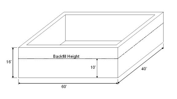
The example problem will be a 40 foot by 60 foot building with 12 inch
thick walls and #5 bars spaced at 12 inches in the vertical direction and #6
bars at 12 inches in the horizontal direction on each face of the wall.
The walls are 16 feet high and will be backfilled to a height of 10 feet
with a well-drained granular fill. The
strength of the concrete is assumed to have reached 4000 psi.
A reinforced concrete floor slab will be placed at the top of the walls,
but the constructor would like to determine whether or not the basement could be
backfilled before placing the floor. Figure
2 is a sketch of the structure.
Description
of Structure
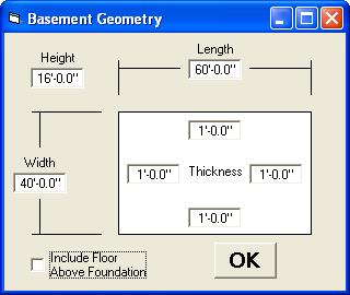
The
input form shown in Fig. 3 prompts the user for the dimensions of the building
and the wall thickness. The user
also specifies whether or not the floor slab is in place.
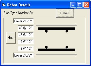
Reinforcement information for each wall is input in the form shown in
Fig. 4. The Cover dimension is
expressing in inches and eighths of an inch.
The Hout button indicates that the horizontal reinforcement is on
the outside nearest the surface of the wall.
This can be clicked tp change the caption to Vout indicating that
the vertical reinforcement is on the outside.
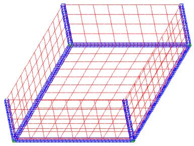
The finite element model shown in Fig. 5 is then generated by selecting
an option on the main menu.
Definition
of Loads
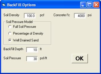
Information
about the loads on the foundation is input using the form shown in Fig. 6.
The soil loads are modeled as a linearly-increasing pressure on the
outside face of the walls. The user
must make decisions to determine the rate at which the pressure increases with
depth (Fletcher and Smoots, 1974). They
may use the default, conservative case which models the soil as a fluid with a
density equal to that of the soil or seek information to justify more realistic
loads. A help system may be
included with the program to assist the user with selecting the correct model.
|
|
|
Figure
2: Structural
configuration |
|
|
|
Figure
3:
Basement Geometry input form. |
|
|
|
Figure
4: Form to input rebar details. |
|
|
|
Figure
5: Basement finite element model with red
shell elements and blue superelements. |
|
|
|
Figure
6: . Form to input backfill information. |
Results
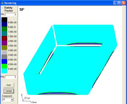
The
results plot shown in Fig. 7 shows the safety factor in all regions of the
model. The safety factor is the
design strength divided by the required strength given the imposed loads.
Safety factors are calculated at each point for both shear and flexural
responses and the lowest value is reported.
The user must decide what safety factor is acceptable.
In this case the lowest safety factor is greater than three, which
indicates that the proposed backfill operation is safe.
If
the safety factor is near to or less than one, the user can repeat the analysis
to investigate other options. Possible
courses of action include: 1) consulting a geotechnical engineer to determine
whether their value for soil pressure was realistic, 2) determining the required
concrete strength to develop an adequate safety factor and estimating if and
when the concrete may reach this strength, 3) evaluating the structural response
with the floor in place, or 4) modeling other backfill depths to determine
whether a partial backfill at this time would be permitted.
|
|
|
Figure
7. Safety factor plot. |
Conclusions
Finite-element-based
structural analysis methods may be used to aid the decision making process in
construction. Well-developed user
interfaces are required so the occasional user can quickly obtain valid results.
A technically competent individual who understands the assumptions used
in the analysis must still interpret these results.
The results must be used in the context of their experience and input
from other sources involved in the construction.
As with any software used in the design and analysis of structures, the
user must be aware that they are still ultimately responsible for the proper
evaluation, interpretation and use of the results.
References
Arumala,
J. (2002). Student-centered activities to enhance the study of structures.
International Proceedings of the 38th Annual Conference, Associated
Schools of Construction, 1-8.
Fletcher,
G.A. & Smoots V.A. (1974). Construction
guide for soils and foundations. New York: John Wiley & Sons.
Opfer,
N.D. & Gambatese J.A. (1999) Temporary construction structures coursework,
Proceedings of the 35th Annual Conference, Associated Schools of
Construction, 231-239.
Slattery,
K.T. (2002). Automated design and analysis of marine structures during
“in-the-wet” construction. International Proceedings of the 38th
Annual Conference, Associated Schools of Construction, 319-324.
US
Army Corps of Engineers. (2003A).
Design by analysis of innovative navigation structures, theoretical manual.
(Technical Report TBD). Vicksburg, MS.
US
Army Corps of Engineers. (2003B).
Design by analysis of innovative navigation structures, user manual.
(Technical Report TBD). Vicksburg, MS.
Weaver,
W., Jr. & Johnston P.R. (1984). Finite
elements for structural analysis. Englewood Cliffs, NJ: Prentice-Hall.