![]()
![]()
![]()
- ASC Proceedings of the 39th Annual Conference
- Clemson University - Clemson, South Carolina
- April 10-12, 2003 pp 67-78
|
|
|
E-Z Forms 2003: Interactive Spreadsheets for Teaching Concrete Formwork Design
|
|
|
The planning, design and construction of concrete formwork systems are completely the purview of the general contractor and their hired sub contractors. As such, most accredited construction management programs offer some sort of course work relating to concrete formwork. This paper will present a set of interactive Microsoft Excel spreadsheets (E-Z Forms 2003) which were developed as instructional aides for teaching construction management students how to design simple timber-based concrete formwork systems. The E-Z Forms 2003 package contains two separate spreadsheets, E-Z Wall 2003 for the design of vertical formwork systems, and E-Z Slab 2003 for the design of horizontal formwork systems. These two spreadsheets are organized in such a fashion as to closely mirror the design process and examples as presented in the 6th edition of Formwork for Concrete (Hurd, 1995), a text recognized by most people in the industry as the standard reference for concrete formwork design in the United States. The bulk of this paper is focused on providing the reader a guided tour through both of these spreadsheets using various screen shots from the programs, and referencing associated information, data and formulas from Hurd’s (1995) Formwork for Concrete. Key
Words:
Timber, Formwork, Design, Interactive Spreadsheets, Instructional Aides |
Whether
structural steel or reinforced concrete framed, all large commercial buildings
today incorporate some cast-in-place concrete.
With the advent of economically feasible, higher and higher strength
concretes, many of the large building concepts that used to be reserved for
structural steel are now being designed and built with reinforced concrete.
Needless to say, concrete is a very important building material, arguably
the most important of all construction materials.
The decision on whether to construct the frame of a building out of
reinforced concrete or structural steel inevitably comes down to a question of
money. And the economics of
reinforced concrete is directly related to the economy of formwork.
Some experts (Hurd, 1995 and Puerifoy & Oberlender, 1996) estimate
that the cost of the formwork can be as much as 60% of the total cost of the
concrete work in place.
In a concrete building, the architect/engineer is responsible for the size, strength, shape and appearance of the structure. However, the planning, design and construction of the materials used to temporarily support these structural components are completely the purview of the general contractor and their hired sub contractors. In fact, there are quite a number of large general contractors across the country who choose to self perform the structural concrete work, which includes the formwork, so that they can better control and drive the construction schedule. Given the fact that cast-in-place concrete is gaining in popularity, and many large general contractors choose to self perform this work, most construction management programs recognize the need to educate their students about concrete formwork. However, with the ongoing pressure to cut units within most programs, and the migration away from pure engineering based curricula, the challenge becomes how to most efficiently teach formwork design without having to spend the majority of the class time bogged down in the details of the engineering calculations.
The idea for this paper is in response to the lead author’s experiences associated with teaching a class in formwork design within a construction management program. Specifically, the class in question is known as CM 444 - Formwork and Other Temporary Structures, and is offered at California Polytechnic State University (Cal Poly) located in San Luis Obispo, California. Based on the learning objectives of the class, the course breaks down into about 70% concrete formwork and about 30% other temporary structures. Add to this the fact that Cal Poly operates on the quarter system (10 week terms), and this translates into about seven weeks of formwork instruction. Given these time constraints, it was the lead author’s concept to have the students focus in on gaining a thorough understanding of how to design one simple timber-based vertical formwork system (a wall), and one simple horizontal system (an elevated flat plate). The authors have found that students are very capable of taking what they have learned about simple formwork design and applying this basic knowledge in their study and subsequent understanding of today’s more complicated horizontal and vertical formworks systems. This paper will present a set of interactive Microsoft Excel spreadsheets (E-Z Forms 2003) which were developed by the lead author as instructional aides for teaching construction management students how to design simple timber-based concrete formwork systems.
As discussed earlier, E-Z Forms 2003 is a set of interactive spreadsheets developed and used by the lead author as instructional aides for teaching simple timber-based formwork design to construction management students. All data and formulas utilized in these spreadsheets are based on information contained in the 6th edition of Formwork for Concrete (Hurd, 1995). This book was selected as the required text for the aforementioned class because it is widely recognized as the standard reference for concrete formwork design in the United States. According to the preface of the 6th edition (Hurd, 1995), this book, known in the industry as “The Green Bible”, has sold over 100,000 copies between 1963 and 1995. Also noted previously was the lead author’s concept of teaching, in detail, one simple vertical formwork system (a wall) and one simple horizontal system (an elevated flat plate) in order to provide a solid background for exploring and studying today’s more complex formwork systems. The E-Z Forms 2003 package therefore contains two separate spreadsheets, E-Z Wall 2003 (for vertical systems) and E-Z Slab 2003 (for horizontal systems). These two spreadsheets are organized in such a fashion as to closely mirror the design process and detailed examples as presented in Hurd’s Formwork for Concrete (1995). The balance of this paper will provide the reader a guided tour through both of the spreadsheets using various screen shots from the programs in which the numbers from Hurd’s (1995) two detailed examples (the Wall Form and Slab Form examples) were input.
Detailed
Look at E-Z Wall 2003 (Based on the Wall Form Example from Hurd, 1995)
Referring
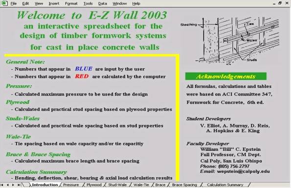
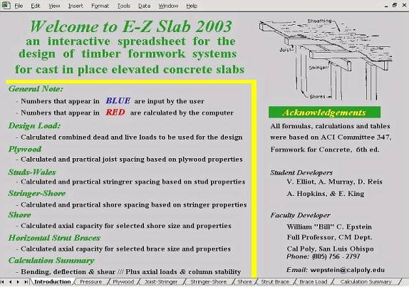
to Figure 1., the reader can see a screen shot from the introduction page of the
E-Z Wall 2003 spreadsheet. One
point of interest is the color scheme utilized by the program; numbers that
appear in blue are input by the user, while the red numbers are calculated by
the computer. Another item to note is the labeled tabs at the bottom of the
screen which represent the sequential steps associated with designing a simple
timber-based wall form system. The
next few paragraphs will discuss details from each of the tabbed sheets,
beginning with calculating the initial design lateral pressure, and finishing
with determining the spacing of the lateral braces.
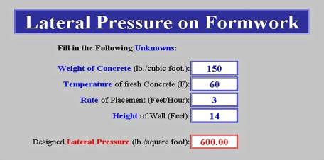
Figure
2. is the tabbed sheet for determining the initial design lateral pressure.
As can be seen, the user inputs all values in blue (weight and
temperature of the concrete, rate of placement, and height of the wall). With this information, the computer calculates the design
pressure assuming the concrete meets “standard conditions” and utilizing the
lateral pressure of concrete equations as per the American Concrete
Institute’s Guide to Formwork for Concrete (ACI, 1994).
These same equations and associated discussions on their appropriate
usage can be found in Chapter 5 of Hurd’s Formwork for Concrete.
In this particular example (the Wall Form Example), based on the given
input, the design pressure will be 600 psf (Hurd, 1995).
|
|
|
Figure 1: E-Z Wall 2003 Introduction Page |
|
|
|
Figure 2: Lateral Pressure on Formwork Design Page |
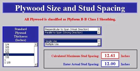
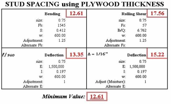
In Figure 3., the reader can see a screen shot of the tabbed sheet in which the user selects the thickness of the plywood, the orientation of the face grain (perpendicular or parallel to span), and the usage factor (single use or multiple use). Based on the Wall Form Example (Hurd, 1995), the user selects 3/4" Plyform B-B Class 1 sheathing, assuming single use and face grain parallel to span. The computer then determines the controlling maximum stud spacing based on bending, deflection and rolling shear calculations (see Figure 4. Stud Spacing Calculation Summary Page). In this example, the controlling stud spacing (based on bending) is 12.61 inches. Assuming an 8 foot module (standard sheet of plywood), the user selects a practical stud spacing of 12 inches, center-to-center (see Figure 3. Plywood Size and Stud Spacing Page).
|
|
|
Figure 3: Plywood Size and Stud Spacing Page |
|
|
|
Figure 4: Stud Spacing Calculation Summary Page |
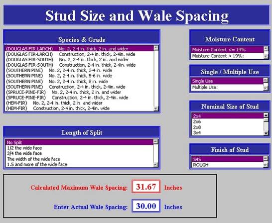
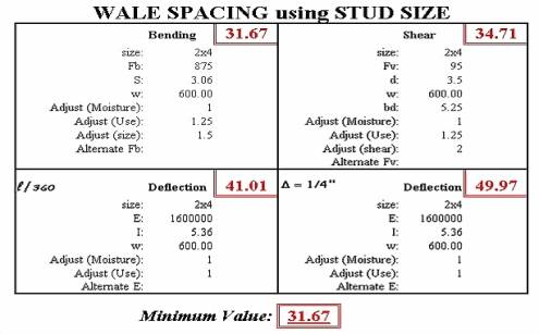
Figure 5. is the tabbed sheet for selecting the stud properties and calculating the controlling wale spacing. In this example, the user selects Douglas Fir-Larch, No. 2, S4S 2x4's, assuming single use, no splits and a moisture content £ 19%. The computer again calculates the maximum wale spacing for this type of stud based on bending, deflection and horizontal shear (see Figure 6. Wale Spacing Calculation Summary Page). In this case, the computer returns a maximum wale spacing of 31.67 inches, with the allowable bending stress again controlling. Based on the wall height of 14 feet (see Figure 2. Lateral Pressure on Formwork Design Page), the user selects a practical wale spacing of 30 inches center-to-center (see Figure 5. Stud Size and Wale Spacing Page).
|
|
|
Figure 5: Stud Size and Wale Spacing Page |
|
|
|
Figure 6: Wale Spacing Calculation Summary Page |
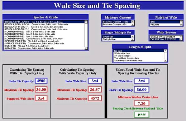
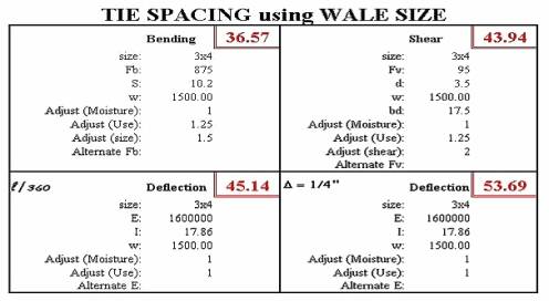
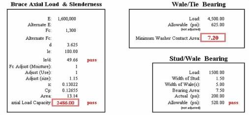
Figure 7. is the tabbed sheet for selecting the wale properties and calculating the controlling tie spacing. In this example, the wale size is unknown, however the user can input the other known properties of the wale system, namely that they are Douglas Fir-Larch, No. 2, S4S double wales, assuming single use, no splits and a moisture content £ 19%. Next, the user inputs the tie capacity in pounds of safe working load (in this case 4,500 pounds). The computer then takes this safe working load and divides it by the uniform load on the wales (1,500 plf) based on the selected practical wale spacing of 30 inches (see Figure 5. Stud Size and Wale Spacing Page). The result of this calculation (4,500 pounds ÷ 1,500 plf = 3 feet) sets the maximum tie spacing based on tie capacity only at 36 inches (3 feet). Next, the computer assumes bending will again control, and applies the allowable bending stress formula, Equation 6-18 (Hurd, 1995), to solve for the minimum Section Modulus (S) required. The computer then sorts the dimensional lumber table records, Table 4-1B (Hurd, 1995) by ascending S values. The spreadsheet is programmed to do a vertical lookup and return the piece of dimensional lumber which has the next higher value of S as compared to the calculated minimum required S. The program will suggest a wale size based on tie capacity only, in this case a 3x4. The user can then input this wale size into the cell entitled “Enter Wale Size:” for “Calculating Tie Spacing With Wale Capacity Only”. The program again runs the calculations for the maximum tie spacing for this type of wale based on bending, deflection and horizontal shear (see Figure 8. Tie Spacing Calculation Summary Page). For this particular example, the computer confirms that bending does control at a maximum tie spacing of 36.57 inches based on wale capacity only (see Figure 7. Wale Size and Tie Spacing Page). Additionally, in Figure 7., the reader can see that the computer calculates a minimum tie capacity of 4,572 lbs (exceeding the selected safe working load of 4,500 pounds) using a 3x4 wale and a tie spacing of 36.57 inches. The user then selects a final wale size and tie spacing, in this case a 3x4 wale was chosen with a tie spacing of 36 inches. The spreadsheet then applies these user input values to calculate the minimum washer contact area on the wales so that the wales will not fail in bearing (allowable compression perpendicular to the grain). And finally, the program checks the bearing stresses between the studs and wales and determines whether or not the allowable compression perpendicular to the grain of either the stud or the wale has been exceeded. In this example, neither of the allowable bearing stresses were exceeded, so the spreadsheet returns a message that indicates that this stud/wale configuration “Passes” the bearing check (see Figure 9. Bearing and Brace Calculation Summary Page).
|
|
|
Figure 7: Wale Size and Tie Spacing Page |
|
|
|
Figure 8: Tie Spacing Calculation Summary Page |
|
|
|
Figure 9: Bearing and Brace Calculation Summary Page |
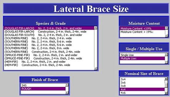
Figure 10. is the tabbed sheet where the user can input the various properties of the lateral bracing. It should be noted that the program assumes that no lacing or bracing will be used. For this particular example, the braces have been selected to be Douglas Fir-Larch, No. 2, rough 4x4's, assuming multiple use and a moisture content £ 19%. In Figure 11., the geometry of the brace is established. For this example, the top of the brace will be connected to the wall at 2 feet from the top of the wall (Dimension D) or 12 feet from the bottom. The bottom of the brace will be attached to the ground at 8 feet out from the base of the wall (Dimension E). Using the Pythagoras Theorem, the maximum length of the brace with the given geometry will be 14.42 feet. Additionally, given the cross section of the brace, the computer determines that the maximum length based on slenderness ratio limitations (l/d £ 50) is 15.10 feet. In this case, the user determines that the design length of the brace will be 15 feet. The design wind load is also established at 20 psf applied at the top of the wall (Dimension A). Based on the brace properties input by the user, the program calculates the axial load capacity of these braces to be 2,486 pounds (Figure 9. - Bearing and Brace Calculation Summary Page). Next, the computer takes the allowable axial load (2,486 pounds) and divides it by the actual axial load of 294.5 plf (see Figure 11. Lateral Brace Spacing Page). This calculation (2,486 pounds ÷ 294.5 plf = 8.44 feet) yields the maximum spacing for the given brace with the given geometry under the given wind load. From here, the user would select a practical spacing based on the length of the wall and modular dimensions, say 8 foot center-to center for the purpose of completing this formwork design example. At this point of the paper, reader has been given a detailed step-by-step tour through the E-Z Wall 2003 spreadsheet. Next, the authors will discuss the other interactive spreadsheet (E-Z Slab 2003). However, this spreadsheet will be presented in more of an overview fashion.
|
|
|
Figure 10: Lateral Brace Size Page |
|
|
|
Figure11: Lateral Brace Spacing Page |
Overview
Look at E-Z Slab 2003 (Based on the Slab Form Example from Hurd, 1995)
This section of the paper will present an overview of the E-Z Slab 2003 spreadsheet, as opposed to the detailed approach that was used in discussing the E-Z Wall 2003 program. Beginning with the introduction page of the spreadsheet, the reader can see in Figure 12., that the same color scheme (numbers appearing in blue are input by the user, and numbers appearing in red are calculated by the computer) is utilized. Additionally, several of the tabbed sheets (Plywood, Joist-Stringer, and Stringer-Shore) are similar in nature to the E-Z Wall 2003 program, and therefore, screen shots from these pages will not be presented. The Vertical Pressure on Formwork Design Page (see Figure 13.) from the E-Z Slab 2003 program however is different enough from the Lateral Pressure Design Page (see Figure 2.) of E-Z Wall 2003 that it warrants mention herein.
|
|
|
Figure12: E-Z Slab 2003 Introduction Page |
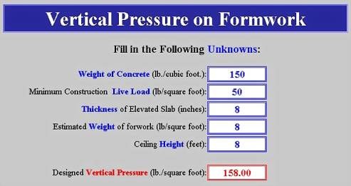
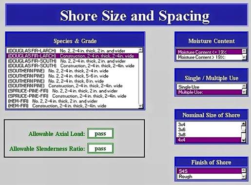
As can be seen in Figure 13., the user inputs values for the weight of the concrete, the live load on the slab, the thickness of the slab, the weight of the formwork, and the ceiling height. The program then calculates the vertical pressure, in this case 158 psf, which matches the Slab Form Example (Hurd, 1995). Once the design pressure is calculated, the plywood sheathing and the spacing for its supports (joists) can be determined in the same fashion used to calculate the stud spacing , as presented previously in the detailed example of the E-Z Wall 2003 program. The next two tabbed sheets (Joist-Stringer and Stringer-Shore) as shown at the bottom of Figure 12. (E-Z Slab 2003 Introduction Page), follow the same procedure for the design of single member beam components as was presented in the E-Z Wall 2003 example (see Figure 5. Stud Size and Wale Spacing Page). At this point in the design, the 3/4" plywood sheathing has been selected with 2x4 joist supports spaced at 19.2 inches center-to-center. Furthermore, 3x6 stringers will be utilized at a spacing of 36 inches and will be supported by 4x4 shores spaced at 45 inches center-to-center. The next step in the process is to design the shores based on their allowable axial load parallel to the grain. Figure 14. is the tabbed sheet where the user can input the shore properties. In this case the shores are Douglas Fir-Larch, Construction Grade, S4S 4x4's, assuming multiple use and a moisture content £ 19%. With this information, the computer then checks the shores for their allowable capacity based on the comparison of actual loads to allowable loads. Additionally, the computer verifies that the slenderness ratio (l/d) does not exceed 50. The summary screen detailing the calculations for the axial load and slenderness ratio of the shoring is very similar to the wall form lateral bracing calculations as shown in Figure 9. (Bearing and Brace Calculation Summary Page), and therefore will not be presented. However, it can be seen in Figure 14., that for this example, the shores pass in both axial load capacity and slenderness ratio criteria.
|
|
|
Figure13: Vertical Pressure on Formwork Design Page |
|
|
|
Figure14: Shore Size and Spacing Page |
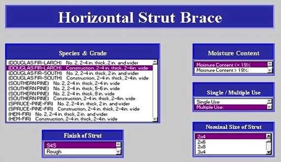
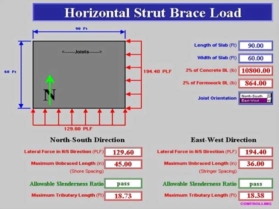
Figure 15. is the tabbed sheet where the user can design the horizontal strut bracing requirements for the elevated deck system. In this example, the user inputs the properties of the strut braces as Douglas Fir-Larch, Construction Grade, S4S 2x4's, assuming multiple use and a moisture content £ 19%. Figure 16. is the sheet where the user tells the computer the overall elevated deck dimensions (90 feet by 60 feet) and the orientation of the joists (East-West). Next, the computer calculates the lateral design load distributed along the slab edge in each direction (194.4 plf in the East-West direction, and 129.6 plf in the North-South direction). The program retrieves the previously established practical stringer and shore spacings (36 inches and 45 inches, respectively) and verifies whether or not the braces will fail in buckling (l/d £ 50). The computer also determines the allowable axial load capacity for the strut braces in either direction. The summary screen detailing the calculations for slenderness ratio and the axial load capacity of the strut braces is again very similar to the wall form lateral bracing calculations as shown in Figure 9. (Bearing and Brace Calculation Summary Page), and therefore will not be presented. Once the axial load capacity of the strut braces is known, the maximum tributary length that these braces can support is calculated. These values of maximum tributary length are determined by taking the actual lateral force (plf) in the direction of the strut brace and dividing this number by the strut’s allowable axial load capacity (pounds) to get a maximum tributary length expressed in foot of slab edge. To finish up this example, the reader can see from Figure 16., that the maximum controlling tributary length is 18.38 feet. Referring to the Slab Form Example (Hurd, 1995), the typical bay layout is 15 feet by 15 feet, therefore indicating that if the strut braces were placed at every row of columns in either direction this configuration would be acceptable, given that the maximum allowable controlling tributary length (18.83 feet) exceeds the actual maximum tributary length of 15 feet.
Conclusion
The main objective of this paper was to give the reader a guided tour of two interactive spreadsheets (E-Z Wall 2003 and E-Z Slab 2003) which were developed as instructional aides for teaching construction management students how to design simple timber-based formwork systems. In this regard, the paper has accomplished this modest goal. However, from a broader point of view, the authors wanted to take the opportunity in these concluding remarks to comment on several of the pedagogical issues associated with these programs. First of all, these spreadsheets serve as excellent in-class presentation tools, enabling the instructor to review various design examples without having to get bogged down in all of the rote calculations. Furthermore, because of the relative reviews the examples from the book, the students can concentrate more on the methods and processes, and not get overly focused in on the details of the calculations presented. And finally, the benefit that seems most important to the student is the concept of receiving immediate feedback when solving complicated design problems outside of the classroom. That is to say, when working on an engineering problem, where the answer from one part of the problem directly affects subsequent steps in the design process, it is very helpful to have a tool that can be used to verify that the solutions arrived at are correct. These spreadsheets can be very useful in developing accurate design solutions rather quickly, however they find their best use in the educational value they provide to the typical construction management student trying to effectively learn how to design simple formwork systems.
ACI Committee 347. (1994). Guide to Formwork for Concrete (ACI 347R-94). Detroit, MI: American Concrete Institute.
Hurd, M. K. (1995). Formwork for Concrete (6th ed.). Detroit, MI: American Concrete Institute.
Peurifoy, R. L. & Oberlender, G. D. (1996). Formwork for Concrete Structures (3rd ed.). New York, NY: McGraw-Hill
|
|
|
Figure15: Horizontal Strut Brace Page |
|
|
|
Figure16: Horizontal Strut Brace Load Page |