![]()
![]()
![]()
- ASC Proceedings of the 39th Annual Conference
- Clemson University - Clemson, South Carolina
- April 10-12, 2003 pp 213-222
|
|
|
Designing
an Integrated Low-Cost Solar Collection System
|
|
Integrating solar collection systems into a building’s shell and mechanical system could enhance the performance of the collector as well as reduce its costs. Historically, solar collection integration has faced four major concerns: thermal performance, aesthetics, cost effectiveness, and building envelope performance. This paper describes how, in order to satisfy the aforementioned concerns, innovative design methodologies can be used to effectively integrate the solar collection system, the building envelope, and the mechanical system. A design iterative process that results in a more energy efficient, cost effective panel is described. Results showed that in terms of cost and thermal performance, the proposed designs can compete effectively with conventional collectors. Key
Words:
Solar Collection, Design Integration, Building Envelope, Thermal
Performance, Concrete |
Introduction
Exploitation
of non-renewable resources (e.g. materials, energy, etc.) can create
non-sustainable conditions and environmental degradation, resulting in a
significant loss of final product quality.
In many industrialized countries, including the United States, the
heating, cooling, ventilation, and lighting of buildings represent approximately
40% of the nation’s annual energy consumption (Hartkopf et. al 1994).
Therefore, it is important to seek alternative methodologies that continue to
improve our quality of life, while reducing energy and environmental
consumption.
In
the past 20 years, interest has grown in developing new methodologies that can
effectively utilize renewable sources of energy, an effort that has yielded a
variety of techniques with differing degrees of promise.
Recently, researchers have strenuously promoted the use of solar energy
as a promising alternative (Ametek
1985). Solar energy possesses characteristics that make it highly attractive as
a primary energy source that can be integrated into local and regional power
supplies; essentially, it represents a sustainable, environmentally friendly
source of energy that can reduce energy costs (Lundsager 1996).
Although recent studies have shown that the use of solar energy is
strongly supported by the US public, its up-front financial expenditures are
greater than those associated with traditional systems, which makes some critics
doubt its overall cost-effectiveness (Rockwell 1999).
In fact, this doubt has led to a certain amount of mistrust among
agencies as to the true long-term benefits of solar-based systems.
In
light of the aforementioned discussion, the objective of this research is to
present a new, more cost-effective methodology for integrating solar energy
collection systems into conventional building structures.
This goal involved rethinking the overall building construction
methodology to balance the increase in cost associated with the solar systems by
a decrease in other construction costs. In
the future, the potential exists for building an instrument to experimentally
test the proposed final design.
Background
System
Integration for Building Performance
The
redesign process relied on integration theory, a process that develops properly
integrated designs by dividing the building into four systems that address its
major functions: structure, interior, envelope and mechanical.
In any buildings, the aforementioned systems are interconnected, and the
nature of the connection identifies the level of integration.
The designer can then investigate alternative levels of integration to
conserve space, material, and time (Rush 1986).
The
level of integration can, however, be constrained by the accepted level of
expected performance. Integration
theory identifies six main performance categories: spatial, thermal, air
quality, acoustical, visual, and building integrity. Each performance category defines the “comfort zone”
accepted by the building’s occupants. It
should be noted that decisions made within each system—structure, envelope,
mechanical or interior—affects different performance categories depending upon
the level of integration.
The
aforementioned six performance criteria are integrative and should be maintained
through proper communication during the building’s delivery process, from the
design stage to the development of the integrated system.
The result will be a building that performs in harmony over time and
fulfills any client’s central requirements: suitability, reliability, and
flexibility (Rush 1986).
Solar Energy Collection System
Integration
Properly
integrating a solar energy collection system into a building’s shell and
mechanical systems could reduce the cost of the system as well improve
collection efficiency. Therefore, research in Building Integrated Solar Thermal
(BIST) design, which started in the early 1940s, continues unabated. In solar
integrated design, the building is used as part of the collection system.
BIST systems have many advantages over normal collection systems,
including their ability of expanding to cover the entire area of the roof at a
reasonable cost. Additionally,
these systems usually have a longer service life, which results in less of a
need to replace materials, as well as in improved conservation.
Solar
integrated designs face four major concerns that affect client acceptance:
thermal performance, building envelope performance, aesthetics, and
cost-effectiveness. Although many
of the proposed designs failed in one or more of these categories, some proved
successful. Unfortunately, even for
the successful designs, the supporting research necessary to improve aesthetics
and performance, as well as lower system costs lagged behind (Archibald 1999).
In
many successful designs, the roof was distinctively used as an integrative
thermal building element, which means that it performed its normal
functions—formation of a thermal and vapor barrier, resistance of wind and
weight of snow and ice, providing of a comfortable environment for the
space—but also collected energy regardless of design (i.e. active, glazed,
unglazed, passive, focusing, or non-focusing).
Combining the function of two separate systems into one resulted in a
cost reduction of up to sixty percent in materials, time, and labor.
Formulation
of the Design Criteria Based on Building Integration
This
research focused on integrating active solar collection systems with the
building’s roofing system. The
primary goal was to integrate the envelope, structure, and mechanical elements
in order to provide better building envelope and thermal performance and to
improve aesthetics at a competitive cost. The
proposed roofing collection system was designed for a single location:
Blacksburg, Virginia.
The
following requirements were satisfied in the formulated design:
1.
Thermal
performance: to provide the
building with heating and hot water, act as an energy storage sink, maintain an
appropriate air temperature, mediate radiant temperature and relative humidity
within the space, and maintain a comfortable level of air movement.
2.
Environmental
design: to design a durable,
flexible and sustainable building.
3.
Building
envelope: to act as part of
a weather tight envelope, prevent precipitation from entering the building, keep
out wind, dust and odor, and control the temperature and humidity inside the
building.
4.
Aesthetics:
to blend the collection system into the building’s architectural makeup and
introduce a marketable product.
5.
Cost-efficiency:
to reduce construction costs, extend the system’s service life, and produce a
competitive alternative to traditional systems.
To
satisfy the aforementioned requirements and create this new solution for
residential construction, a multidisciplinary research team of building
constructors, engineers, and architects was formed. This team was made up of graduate (Masters and PhD) and
undergraduate students from mechanical, building construction, and civil
engineering, and architecture. It started out as an academic exercise then
became a research project, students volunteered to join based on their research
interest. The project has been in operation the past year and a half.
Current
Available Low Cost Flat Plate Solar Collection Systems
A
variety of solar collection techniques exist, including photovoltaic ones that
convert heat energy to electricity and flat plate ones that collect solar energy
to provide heating and hot water requirements. Flat plate collectors were chosen for usage in our research
because of their ability to supply energy at low cost. In addition, they can be
easily integrated within the structural members of the building.
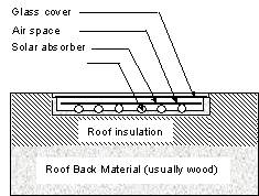
The
flat plate design represents the most economical, active method of solar energy
collection. Such designs consist of
an assembly of transparent covers over an absorber plate backed with thermal
insulation, as shown in Figure 1. The
cover prevents convection losses, reduces thermal radiation losses, and protects
the absorber plate against environmental hazards.
While the absorber is a coated plate upon which the sun’s energy is
converted to heat, the insulation prevents back losses. Flat plate collectors
use absorbers to heat air or water, which can then be used to heat water or
stored for later use. They are usually chosen for applications requiring
moderate heat gain (i.e. 100oC above ambient temperature; ASHRAE
1999).
|
|
|
Figure 1: Flat Plate Collector Components |
Theoretically,
when the sun is directly overhead on a cloudless day, a flat plate collector
with 10m2 of surface could provide energy at 10% efficiency of
collection. That rate of efficiency decreases when convection and radiation
losses occur (Goswami et. al. 2000).
Design
process
The
proposed integrated solar collector roof panels were designed to accommodate the
aforementioned design criteria. This section will examine available alternatives
for achieving the optimum design in terms of thermal performance, environmental
design, building envelope, aesthetics, and cost-effectiveness.
To
accommodate the thermal performance requirements, the integrated roof should
serve three functions: act as an efficient solar flat plate collector, utilize
its thermal capacitance for storage, and retard the propagation of the thermal
energy through the building component. These
criteria can be accomplished by integrating a flat plate collector with a high
thermal inertia material, also known as a thermal mass.
Research has shown that there is great potential for storing thermal
energy within the structure of buildings (Simmonds 1991).
Thermal mass can delay heat transfer through a building component,
resulting in only moderate indoor temperature fluctuations during outdoor
temperature swings. In addition, if properly sized for energy storage and in
comparison to a similar low-mass building, thermal mass reduces the building’s
energy consumption and shifts energy demand during off-peak periods (ASHRAE
1999).
Advantages
that can be attained through thermal mass usage include: reduction of peak
electrical demands; utilization of low nighttime electrical rates, if needed;
offsetting mechanical cooling with free night cooling; and enhancing of
equipment operation at more favorable part-load conditions (Braun 1990).
Therefore, it was decided that this project should utilize a building
material with a high thermal inertia. Table
1 summarizes the thermophysical properties of the different alternative
materials this research could use (after Incropera and De Witt 1996).
As can be seen from Table 1, concrete has the highest thermal capacity,
which indicates that it has the maximum heat storage capacity (1936KJ/m3K).
Although wood can provide a longer time lag, it is more expensive to
manufacture in larger thicknesses.
Table
1
Thermo-Physical
Properties of Building Materials (Incropera and De Witt 1996)
|
Property
Material |
Density
(r) (Kg/m3) |
Thermal
Conductivity (W/mK) |
Specific
Heat (Cp) (J/KgK) |
Thermal
Capacity (rC) (KJ/m3-K) |
Thermal
Diffusivity (a) (cm2/s) |
Time
lag for 1 inch2 (min) |
|
Wood
Plywood |
545 |
0.12 |
1215 |
662.2 |
1.81
x 10-3 |
59.41 |
|
Wood
Hardwoods (Oak, Maple) |
545 |
0.16 |
2400 |
1308 |
1.22
x 10-3 |
88.13 |
|
Wood
Softwoods (Fir, Pine) |
510 |
0.12 |
1380 |
703.8 |
1.71
x 10-3 |
62.88 |
|
Concrete |
2200 |
0.81 |
880 |
1936 |
4.1
x 10-3 |
26.22 |
|
Masonry
Brick |
1920 |
0.72 |
835 |
1603.2 |
4.5
x 10-3 |
23.89 |
|
Masonry
cement mortar |
1860 |
0.72 |
780 |
1450.8 |
4.9
x 10-3 |
21.94 |
Environmental Design
The
environmental requirement allows the proposed system to function in harmony with
its surroundings. The solar
collector integrated roof was located on the building’s façade in a position
that would allow it to capture the largest amount of solar energy.
In order to assure maximum solar exposure, it was also inclined at an
equivalent angle to its location’s latitude. Since this research models a case
study located in Blacksburg, Virginia, the integrated solar roof will be located
on the south façade and +/- 30 degrees from south at an inclined angle of 37o.
One
of the key features of such a system is flexibility, the ability to achieve any
desired shape, finish or geometry at any point in time to adapt to changing
functions and occupancies. The
system created for this research project was designed for maximum flexibility.
In order to achieve this objective, the appropriate building system
should be capable of taking many desired forms or geometries at a competitive
cost. Negative formwork was used to
achieve this objective. These forms
are manufactured by spraying polyurethane foam on a material that gives the
desired surface finish, such as stone, and color pigments can be added to
achieve a natural tone. When the
polyurethane hardens, it is stripped off and used as the inner lining of the
formwork for the concrete system. The
outer lining gives rigidity to the formwork and can be made out of wood or
plastic. Such formwork can be used
to produce a minimum of 5000 panels, which makes the process attractive, cost
effective, and easy to incorporate into an industrialized production line.
A
system must also be reliable. Reliability is defined as the probability that,
given proper maintenance, performance will continue as intended through the
building’s life. Current
construction practices indicate that the
use of layered construction has been increasing for the past decade and, along
with it, so has the need for maintenance, increasing specialization of trade,
and increasing losses of time and money. Therefore, a goal of this research is
to eliminate layered construction in order to minimize system failure and
increase reliability. Utilizing
negative formwork with a concrete system allows for construction of single
composite systems. The polyurethane and concrete layers are structurally joined using high
strength, low conductive fiber composite connectors that are flexible to allow
for different volumetric changes. They
are also strong enough to resist forces placed on the panel that could otherwise
lead to stripping. Such connectors
come in various forms: a C tie, a hairpin tie, a No. 2 tie, a Stirrup tie,
or a plastic nail. When embedded in concrete, even during freeze-thaw cycles,
they experienced no loss in strength. A key advantage of such connection
techniques involves elimination of the bridging effect that occurs when metal
ties are used (Sauter 1991).
Finally,
such a system must also be sustainable: together
with its integrated parts, it must serve the user’s needs in the present as
well as in the future. Therefore
the system is required to be durable as well as resistant to natural disasters
including floods, hurricanes, and fires. Concrete
structures can be designed for a service life of up to 100 years and can use
available technology to accommodate the aforementioned requirements.
Building
Envelope
Reinforced
concrete building shells have a proven ability to keep out wind, dust, and odor.
If properly insulated, they can prevent precipitation from entering the
building and help control the temperature and humidity, thereby satisfying the
building envelope requirements.
Aesthetics
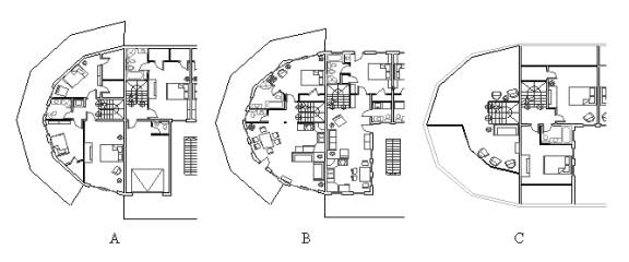
The architecture team working on this project has developed a design that evolved over time from a 12 sided, three-story townhouse, as shown in Figure 2, to a structure that combines rectangular and six-sided shapes, as shown in Figure 3. Floor plans for the final design are shown in Figure 4.
|
|
|
Figure
2: Initial Design |
|
|
|
Figure3:
3D
Sketch of the Final Design |
|
|
|
Figure
4: 3D
Floor Plans of the Final Design a) Basement b) First Floor c) Loft |
|
Integrated
Roof Solar Collector Description
Design
of the integrated roof solar collector was shaped by an iterative process of
design, performance evaluation and redesign. Two alternatives reached the final
stages of design. A cross-section
of the first design is shown in Figure 5. It consists of a 6.35 mm (0.25 inch)
single glass panel with an e-coating on the inner surface, followed by an
air-gap. The thermal collecting
medium consists of a fluid (water with antifreeze) enclosed in 12.7 mm (0.5
inch) diameter copper pipes painted black to ensure maximum solar absorption.
|
|
|
Figure
5: Cross
Section of the First Integrated Design |
The
pipes are laid within concrete cavities to minimize construction cost and time,
as well as to reduce convection losses. They
are surrounded with aluminum foil to ensure reflection of any radiation hitting
the inner surfaces of the concrete cavity back to hit the copper pipes.
The fluid absorbs the solar energy and transports it to storage
locations. The copper pipes are connected by the aluminum foil layer
surrounding them. The parts of the
aluminum foil not surrounding the pipes are also painted black to ensure
maximization of the absorbed radiation. The
foil absorbs the solar radiation and transmits it to the pipes by conduction (Duffie
and Beckman 1980). The copper pipes
are placed in groups of three every 800 mm (31.5 inch), a distance selected to
maximize temperature gain while minimizing panel cost.
A
50.8-mm (2.0 inch) layer of insulation is attached to the back of the aluminum
foil to reduce heat transfer to the adjacent 76.2 mm (3.0 inch) concrete.
A 76.2-mm (3.0 inch) concrete layer is used to prevent growth of microbes
in the polyurethane layer and thus ensure healthy air quality within the system.
Polyurethane foam 76.2-mm (3.0 inches) thick is placed after the concrete
to act as an insulation layer. The
last layer consists of concrete 76.2 mm (3.0 inches) in thickness to ensure
structural stability as well as contribute to the thermal inertia on the inside
of the facility. The panel is
connected by the aformentioned fiber-reinforced plastic stirrups, commonly used
in slab construction, to provide tensile and shear strength. Such stirrups help
the panel function as a composite system, rather than a multi-layer one, and
resist temperature and loading changes (Sauter 1991).
To
quantify the benefits of the first new design, finite element models were
developed to predict the integrated solar collector’s thermal performance and
compare it to that of traditional flat plate collector designs.
ABAQUS Software, Version 5.8 was used for the finite element modeling of
the solar roof panels (ABAQUS 1998). The developed finite element code
represents the solar panel shown in Figure 1, with a length and width of a
typically inclined two or three-story building roof. The roof’s incline is an
input parameter (modeled at 37o to maximize solar gain). To
investigate the solar panel’s effectiveness, three dimensional models were
developed. The dimensions of the modeled portion are, in each case, 3500mm x
1500mm (138.0 inch x 59.0 inch). These dimensions were selected to reduce any
edge effect errors while keeping the element size within acceptable limits
(modeling constraints). The roof panel geometry dictated the element types and
dimensions. Rectangular (DC3D8-brick) continuum elements (with a “brick”
defined as an 8-noded element) were selected for all materials in the 3D model,
except for the fluids, where rectangular (DCC3D8-brick) continuum elements were
used to simulate the forced convection taking place.
Solar
intensity and inside and outside temperatures are assumed to be user-defined,
taken from weather data in TMY2 files. A convection boundary condition and a
solar radiant flux govern the heat exchange taking place between the environment
and the glass surface. The convection coefficient (hc) is defined as
follows (Duffie and Beckman 1980):
hc
= max [5, 8.6(V0.6/L0.4)] (1)
Where,
v is the wind speed in m/s, and;
L
is the cube root of the house’s volume.
As
it passes through the glass, the radiative flux is reduced according to its
angle of incidence. It passes through a subroutine that calculates the
absorption, reflection, and transmittance according to the properties of the
glass.
In
comparison to that of traditional flat panels, results showed superior
performance of the new design (Hassan and Beliveau 2003).
Other benefits include a significant reduction in construction costs:
while the traditional flat plate solar collector costs $24 per square foot, the
proposed integrated roof collector is a mere $15. In addition, use of a
composite single system requires the presence of fewer trade representatives on
site, thereby reducing labors costs. Additional savings can be achieved because
the single-layer system requires less maintenance. Finally, another source of
savings may be the use of precasting techniques and rapid in-place assembly,
which in combination also reduce construction time and labor.
|
|
|
Figure
6: Cross
Section of the Second Integrated Design |
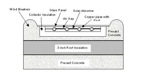
Unfortunately,
early evaluations of the aforementioned design showed that it is difficult to
construct and requires skilled labor. Therefore, it was simplified further,
culminating in the design shown in Figure 6. As can be seen in this figure, the
upper layer of concrete is covered with a layer of insulation and the circular
concrete cavities are replaced with a 610 mm (2 ft) square cavity containing
four 12.7 mm (0.5 inch) connected pipes. This
alteration further simplifies construction. To reduce the wind speed that
results in convection coefficient and losses, the concrete has 76.2mm (3 inch)
semi- cylindrical wind breakers placed every 610 mm (2 ft). The section shown in
Figure 6 is repeated along the roof as needed to satisfy the building’s
heating and hot water requirements. The
rest of the features remain the same as in the first design. With this revised
model, cost and results improved. The cost of constructing the second design is
around $10per square foot. Finite element analysis models also indicated that,
when compared to that of traditional flat plate collectors, performance of the
second model was superior.
Summary
A
design process was presented for utilizing construction materials and techniques
in the proper integration of low cost solar collection systems with the roof
elements of residential buildings. Such
integration can enhance the performance of the collection system as well as
reduce its costs. The necessity for
proper integration justified the need to evaluate the building design process.
This paper summarizes the design process and presents the final design
alternatives for the building integrated solar thermal roofing system. There is
a possibility that construction of the designed system will begin in 2003. In
that case, the building will be instrumented to evaluate and validate the
design’s effectiveness and long-term benefits.
References
Ametek. (1985). Solar
Energy Handbook. Chilton Book Company, Pennsylvania.
Archibald,
J. (1999). Building Integrated Solar Thermal Roofing systems History, Current
Status, and Future Promise. Proceedings of
the Solar 99 Conference, American Solar Energy Society (ASES), 95-100.
ASHRAE.
(1999). Ashrae Handbook Heating,
Ventilation and Air Conditioning Applications. Atlanta.
Braun,
J. (1990). Reducing Energy Costs and Peak Electrical Demand through Optimal
Control of Building Thermal Storage. Ashrae
Transactions 96(2), 876-885.
Duffie,
J., & W. Beckman, W. (1980). Solar
Engineering of Thermal Processes. New York: John Wiley & Sons.
Hartkopf,
V., Loftness V., & Duckworth,
S. (1994). The Intelligent Workplace Retrofit Initiative. DOE Building Studies.
Hassan
M. H., Beliveau, Y., Thomas J., & Jones J. (2003), Finite Element Modeling
of a Specially Designed Solar Roof. Proceeding
of the International Conference on Arts and Humanities.
Incropera,
F. P., & De Witt, D. P. (1996). Fundamentals
of Heat and Mass Transfer. New York: John Wiley & Sons.
Lundsager,
P. (1996), Integration of Renewable Energy into Local and Regional Power Supply.
The World Renewable Energy Congress,
Denver, 117-122.
Rockwell,
K. (1999), The Big Picture-Building Solar Hot Water System With Conventional
Energy Efficiency. Proceedings of The
Solar 99 Conference, American Solar Energy Society (ASES), 281-284.
Rush,
R. D. (1986). The building Systems
Integration Handbook. The American institute of Architects.
Sauter,
E. (1991). Insulated Concrete Sandwich Walls, Exterior Wall Systems: Glass and
Concrete Technology Design and Construction. ASTM STP 1034, 170-186.
Simmonds,
P. (1991). The Utilization and optimization of a building’s thermal inertia in
minimizing the overall energy use. Ashrae
Transactions, 97(2), 1031-1042.