|
(pressing HOME will start a new search)
|
|
DESIGN BY ANALYSIS TOOL FOR TEACHING FORMWORK DESIGN
Kerry T. Slattery
Southern Illinois University
Edwardsville, Illinois
Concrete formwork is a temporary structure that is usually designed by the constructor. Construction textbooks typically just address the design of simple wall and slab forms. Given the constraints on the curriculum, it may only be feasible to pursue this level of complexity. However, the construction student, as well as the constructor in the field, should have an appreciation for the challenges of designing more complex formwork. A tool that would provide an interactive graphical interface and automate the analysis task can provide a means for developing an understanding of the response of these structures and be used to design and optimize formwork. "Design by analysis" implies a design environment in which the structure is described parametrically or graphically, iterations on the design are quickly analyzed, and the designer can easily respond to feedback from the analysis to improve the design. A computer program is currently being developed to perform design by analysis on concrete formwork. At this preliminary stage of development, the shape of a concrete wall is input in an interactive graphical environment. Sheathing, studs, wales and ties are automatically generated based on initial spacings input by the designer. The designer can then revise the design using Move, Copy and Modify commands. A finite element model is automatically generated and analyzed, and results are plotted on the model indicating regions of excessive deflection or stress. This design can be updated and reanalyzed in a seamless process until all design criteria are satisfied.
Keywords: Formwork, Finite Element, Design, Analysis, Automation
Introduction
Formwork failure is a major cause of construction injuries and will negatively impact the cost and schedule of a project. Even minor "failures" which are braced during concrete placement cause distortions in the finished surface that usually have to be repaired after form removal. Failure can sometimes be prevented by conservative formwork design, but this increases cost and is not always effective if the actual failure mode is not addressed in the design. Since the constructor is responsible for formwork design, their training must be adequate to identify and design for all potential failure modes. Simple wall and slab form design can be addressed in the construction curriculum, but issues involving complex form geometry, connections, incorporation of modular formwork components, and overall structural response are usually beyond the scope of these courses. A formwork design aid that allows students to study more complex structural design issues without requiring extensive additional training could be used in the construction curriculum to develop a better appreciation for structural response. With additional development and testing, the constructor in the field could use the same tool to improve formwork design, efficiency and safety.
A finite-element-based, "design by analysis" computer program is currently being developed to augment courses in Construction Methods and Concrete and Formwork. In the earlier, Sophomore-level course, design requirements are discussed for both wall and slab forms. The typical structural configurations are described, and a simple example is solved using a spreadsheet without discussing the structural theory behind the calculations. An interactive analysis tool with a graphical interface can be used at this level to demonstrate the effect of design changes to the class. For example, with current technology changes in input cells in the spreadsheet cause numerical output values such as critical length to change in other cells. The student is required to mentally translate this numerical change to the physical response of the form – a difficult process for an inexperienced designer. With the design by analysis program, a wale can be "dragged" 4 inches and the supported stud will change colors where the flexural stress now exceeds the allowable. This provides an immediate picture of the physical effect of changes in the design parameters on the response leading to improved understanding of the structural response.
In the Junior/Senior level class, the students learn the design approach for formwork with its simplifying assumptions. The design by analysis tool will be distributed to the students to study the effects of these assumptions on the design and to optimize the formwork. They will start with an initial design and move, add and delete members until all design criteria are satisfied. As the development of the design by analysis tool progresses, more complex problems can be introduced and studied.
Design by Analysis
In the conventional design process, a designer lays out the structure based on the functional requirements and determines preliminary member sizes based on experience or simplified structural models. The design then moves to the analysis phase where more accurate techniques are used to determine the structural response and to check the design assumptions. Changes are discouraged as long as the structure is adequate since it is expensive to go back to the designer, make the necessary changes, and repeat the analysis. This approach typically produces conservative designs because the designer wants to get it right the first time. Formwork design rarely even goes through an "analyst" for reasons of cost, schedule, practicality and tradition. In this case the designer may tend to be more conservative because more accurate analysis techniques are not available and the critical independent check of the design assumptions may be bypassed. The Design by Analysis approach attempts to dramatically increase the efficiency of the design – analysis loop in order to encourage many design updates based on analysis results leading to better designs.
Objectives
The objectives of the development of Design by Analysis software for formwork are to: 1) automate the layout and documentation of the formwork, 2) merge design and analysis into a seamless process, 3) optimize the design, and 4) promote a learning process for the formwork designer. The software must run on a Pentium-based personal computer. The inexperienced user should be able to input the parameters for a model by following procedures that are clearly explained by the program. Immediate feedback must be provided to verify the inputs, and sketches of the completed design made available to give to the person fabricating the formwork. The user should be able to "build" and modify the formwork on the computer screen by moving components with the mouse. The Design by Analysis software then allows the user to perform virtual experiments to promote the optimization and learning process.
Approach
Design by Analysis combines the design and analysis functions in one "seamless" loop. Ideally, a single computer program allows the user to input the model, analyze it, view the results, revise and reanalyze the model as many times as necessary, and provide output for design documents. The structure is described parametrically and/or graphically to allow the user to quickly update the design during each design iteration. All properties of the analytical model are tied to the parametric/graphical description so the analysis can proceed directly from the model updates. The analysis must be performed quickly – preferably in 2 to 3 seconds – to maintain the user’s attention. This will require the development of faster analytical methods for large models, but the current approach, which simply recreates and reanalyzes the entire model after each change, provides adequate speed for many useful models.
Analysis results are presented on the graphical model. These can range from simple labels showing where allowable stresses or deflections are exceeded to contour plots showing actual magnitudes or margins of safety. In any case, the designer sees the effect of design changes in a format that can be quickly understood. The identification and selection of options for correcting design deficiencies will become more intuitive as the designer gains experience.
Finite Element Approach
The finite element method has developed over the past 50 years as the preferred method for performing structural analysis, primarily because it is well suited for solution on digital computers. Structural elements are defined by their geometry (locations of nodes defining the shape) and structural properties (e.g. Young’s modulus, moment of inertia, etc.). Element stiffness matrices are generated using a standard, repeatable approach based on these properties and assembled in to a global stiffness matrix. After defining loads and boundary conditions, a set of simultaneous equations is solved to determine the nodal displacements, which are then used to calculate member strains and stresses.
Methods for analyzing a typical structure are well established. However, the focus of much development over the past decade has been to simplify model creation and the interpretation of results. A model with a couple thousand degrees of freedom can be assembled and solved in a few seconds on current Pentium-based personal computers, but it can take days to describe the geometry and create the input file. General-purpose preprocessors can accelerate this process, but they require a trained and experienced operator. A special-purpose computer program can be designed to automate model development for a focussed application. When the user’s options are limited to a subset of those required for a general-purpose program, the novice user with general experience in the design of that application can quickly develop the proficiency needed to use a special-purpose finite element program. There is a valid concern that inexperienced designers should not use the finite element technique as a "black box". The designer is responsible for the final product and must have the experience to identify gross errors in the results. A well-designed, special-purpose, finite element program will prevent many of these errors and identify potential problems that may be missed by an unaided designer.
Implementation
Design by Analysis of formwork begins with a description of the desired concrete structure in the interactive graphical environment. Structural elements for an initial design are then generated based on user inputs and displayed on the model. A finite element mesh is generated automatically and analyzed, and regions of the form in which deflections or stresses exceed the allowable values are identified in the graphical output. The designer can then modify and reanalyze the model until the desired result is obtained.
The concrete structure is described in an interactive, three-dimensional modeling environment. In the current development, all concrete elements must be rectangular and aligned with the XYZ coordinate axes, so a "brick" is defined by inputting the coordinates of two opposite corners. These coordinates can be typed in or selected with the mouse using the up and down arrows to change the Z coordinate. The plot of the concrete element can then be viewed from any angle. Figure 1 shows the modeling environment with a 7-foot long by 8-foot high by 1-foot thick concrete wall.
|
|
|
Figure 1. Concrete Model |
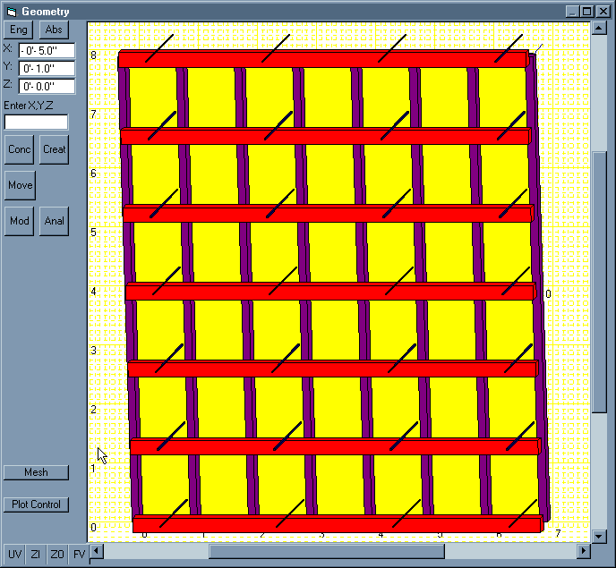
After the concrete geometry is input to the model, the user clicks the Create button. The Formwork Parameters form shown in Fig. 2 becomes visible and allows the user to modify the default design parameters. The sheathing, studs, wales and ties are generated automatically as shown in Fig. 3. The geometric properties of these members were "hardwired" for this demonstration, but the user will be able to select from standard lumber sizes or a library of typical modular form components in later program enhancements. A plate element is currently used for the plywood sheathing with properties derived from the thickness and material properties. The user will be able to input effective flexural properties in the X and Y directions for the plate elements or select from a catalogue of standard industry brands in future versions. The concrete is not plotted in Fig. 3 to show the actual formwork model. For simplicity, only one side of the form is modeled with the ties fixed at the middle of the wall. The ties are plotted on "top" of the model. Most of the ties are actually partially hidden by other form components.
|
|
|
Figure 2. Formwork Parameters |
|
|
|
Figure 3. Formwork Model |
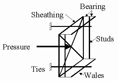
Clicking the Mesh button generates the finite element mesh for the formwork. The sheathing is modeled as four-node plate elements with the corner nodes coinciding with the intersections of the studs and wales. Studs, wales and ties are modeled with beam elements with nodes placed at all intersection points. Additional beam elements are used to model the bearing of one element on another; for example, the stud and wale elements are placed on the centerline of the actual structural member. The nodes where these elements touch are connected with a bearing element perpendicular to the sheathing. Element properties are selected to approximate the behavior of the wood in this direction. Figure 4 is a sketch showing the finite element configuration. Pressure is applied to the model based on the depth of the sheathing element. The pressure varies linearly from the top of the form until the maximum pressure (a function of placement rate and temperature) is reached.
|
|
|
Figure 4. Finite Element Model |
|
|
|
Figure 5. Initial Result with 6 Wales |
|
|
|
Figure 6. Final Design with 6 Wales |
Example
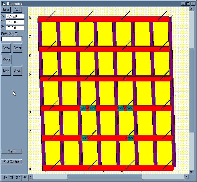
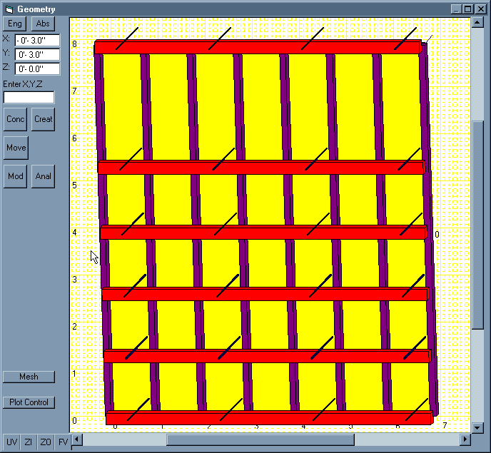
The model described in Figs. 2 and 3 is an 8-foot wall placed at 4 ft/hr and 90° F. The initial spacing is based on standard formwork design procedures. The analysis indicated that all members were within design allowables, as expected. The model was regenerated with an increased wale spacing of 19.2 inches (5 spaces over 8 feet). The results plotted in Fig. 5 show that the shear stress in some web members (WV) exceeds the design allowable; therefore, some design modification is required. The existing wales were moved down to reduce the spacing at the bottom where the maximum concrete pressure is exerted. Figure 6 shows the result of the redesign with an adequate form using one fewer wale than in the initial design. This result may seem impractical, at first, because a uniform spacing is not maintained. However, if a carpenter were handed a copy of this sketch with simple dimensions showing the wale spacing, it could be fabricated in less time with less material
Conclusions
Design by Analysis software for formwork is under development and promises to provide a useful tool for teaching formwork design to construction students. Demonstrations in introductory construction classes will graphically show students the issues involved in formwork design. The instructor can quickly lead the students through "what-if" exercises by changing design parameters and observing the analytical results. After further development and testing, the program will be distributed to advanced students to gain practice and experience in dealing with complex formwork design issues.
Author Notes
The author is an Assistant Professor in the Department of Construction, Southern Illinois University in Edwardsville


