|
(pressing HOME will start a new search)
|
|
Enhancing Value Engineering by Integrating CAD and Estimating Software
|
Value engineering (VE) is a proven management tool to ensure the best functional balance between the cost, reliability, and performance of construction projects. VE is one of several preconstruction activities that are performed to enable clients to make intelligent and informed decisions about constructing their facilities. In a VE study, initial and follow on costs of various design alternatives, should be weighed against other important non-economic criteria such as aesthetics. The best alternative that achieves owner’s requirements with the least life-cycle cost should be selected. Often, however, due to time restraints, a comprehensive study of the impact of various alternatives on cost and aesthetics is not performed. A lack of such a study often leads to a low cost building with poor aesthetics. This has led some designers to think of VE as a cheapening process that cut cost by substituting items, materials, systems that do not meet owner requirements.
The effectiveness of value engineering can be improved by enabling designers to quickly assess the impact of cost reduction ideas on the aesthetics of the building. This can be achieved through the integration of computer-aided design (CAD) systems and estimating software. This paper discusses such integration and describes its application in performing a VE engineering study on the exterior wall of an office building.
Introduction
Value Engineering (VE) is a creative systematized approach whose objective is to seek the best balance among the cost, reliability, and performance of a project (Dell’Isola 1982). It is an important link in the design/construct/maintain continuum. The importance of value engineering has increased during the past few years. One reason for this increase is rising construction, operation and maintenance cost of facilities. Another reason is the growing popularity of alternative project delivery systems (i.e. design/build, construction management) that require early involvement of construction personnel in the design process.
VE proposals can be grouped into two main categories (Elzarka et al. 1998): functional modification and systems modification. Functional modification’s proposals recommend changes in the building scope that will reduce overall cost but still meet owner requirements. An example of such proposal may include changing area distributions to allow for better circulation within the building. System modification’s proposals recommend changes in building systems (e.g. exterior closure system) that might change the aesthetics of the building but will not change building’s scope or net area. An example of such proposal may include substituting a glass curtain wall with a brick-veneer wall.
While value engineering in the construction industry has increased during the past few years, a challenge remains in effectively assessing the impact of cost reductions ideas on the aesthetics of the buildings. This has led in many cases to low cost buildings with poor aesthetics and spread the belief that VE is a cheapening process that cut cost by substituting items, materials, systems that do not meet owner requirements.
There are a multitude of combinations of design, materials and methods that can be used to achieve the ultimate goal of a project. The optimal design should include the best balance between cost and aesthetics. A VE analysis usually looks at the cost of various design alternatives that can be used to achieve owner’s requirements. The number of alternatives considered in arriving at a final design greatly influences the cost of a project. Often, due to the time restraints of the design schedule and budget, the number of design alternatives considered is limited. The lack of time is one reason unnecessary cost gets into the design (Zimmerman et al. 1982).
The discussion above illustrates that the effectiveness of value engineering can be improved by enabling designers to quickly assess the impact of cost reduction ideas on the aesthetics of the building. This can be achieved through the integration of computer-aided design (CAD) systems and estimating software. Such integration would enable the rapid generation of several design alternatives whose cost and aesthetic appeal can be evaluated and compared for achieving optimum value. This paper discusses such integration and describes its application in performing a VE engineering study on the exterior wall of an office building.
Value engineering of Exterior Wall Systems
The design of exterior wall systems represents one of the most challenging segments of construction practice. The function of the exterior wall is to protect against natural forces including rain, wind, temperature changes, and earthquake forces. The design process should select an exterior wall system that provides the required protection while optimizing the value of the entire project. Both the value and aesthetic of the exterior wall system are affected by many factors including (Nashed 1996):
Detailing. Designs that mandate exotic materials and a high degree of skill and precision in construction are expensive. Concentrating on a few focal points such as entrances on which to use choice materials while using less costly construction on the rest of the building reduces cost while maintaining aesthetic appeal.
Use of multiple materials. Designs that subdivide the wall into little areas or require the use of many different materials and finishes inflate the overall cost of the wall. Each different material may require installation by a different trade causing a scheduling nightmare and possible delays. Little panels require an excessive amount of sealed joints adding to the cost of material and labor and an increased likelihood of leakage and increased maintenance cost. Also the use of different materials require the architect to produce more details and more shop drawing checking and site visits to make sure that each one is constructed properly.
Custom designed systems. Custom designed wall systems cost more than off-the-shelf products. Using off-the shelf products reduces liability for problems that may develop later. This is especially true for complicated products such as custom windows. All new products of that type require the expertise of a person specializing in that area. Every new product requires modifications to iron out any flaws before being mass-produced.
When considering each of the above factors to compare between different design alternative, it should be noted that each alternative must meet minimum cost and aesthetic requirements. The comparison should not be between an alternative having an unsuitable looking facility vs. one having a very expensive initial cost.
Computer Aided Design (CAD) Systems
Computer-aided design (CAD) has been widely used in the construction industry. Its use however has been limited to drafting for so many years that it is sometimes referred to as computer aided drafting. When integrating computer-aided design (CAD) into the design process, architectural professionals need to consider software that provides not only superior drafting tools, but tools that are very specific to their other design needs. New CAD tools that are based on AutoCAD have been developed to make the architectural work process more productive. That process includes conceptual design, design development, and construction documentation.
Examples of the new architectural tools discussed above are ArchT from Ketiv Technologies and AutoCAD Architectural Desktop from Autodesk. ArchT is the CAD tool used in the research discussed in this paper. ArchT clients range from large, multi-discipline / multi-national architectural firms to individual architects and design professionals (Ketiv 1997a). ArchT software is highly customizable and can adapt to a wide variety of design and design/build situations.
ArchT has been engineered so that, in the design stage, intelligent architectural objects, such as walls, doors, and windows can be created and added to a drawing in a three-dimensional (3D)-modeling environment. These objects are intelligent because they know their form, fit, and function and their relationships with other drawing objects. For example, when a door is removed from a wall, the wall automatically cleans-up (Ketiv 1997a).
The use of intelligent objects increases the speed of design generation and permits the designer to apply and define different styles for primary building objects such as walls, doors, and windows. Users have substantial design flexibility as object style definitions may be changed or updated at any time. For example, changing wood-stud walls to a CMU (concrete masonry unit) is as simple as choosing the appropriate wall style definition in a dialog box. By changing the definition, all the wood-stud walls in the drawing are updated- without additional drafting.
The 3D modeling environment of ArchT, its direct links to the built-in rendering features of AutoCAD, and the ease of changing its object styles makes ArchT a powerful design tool. The architect can easily explore design alternatives and evaluate their aesthetic appeal earlier in the process when it is most cost-effective. When these capabilities are coupled with the ability to automatically generate accurate cost estimates, the system becomes a powerful VE tool.
Computer-based Estimating Systems
In recent years, computer-based estimating systems have gained wide acceptance in the construction industry. These systems offer several advantages in all the estimating phases namely takeoff, pricing, summarization and reporting.
In the takeoff phase, computer based systems have dramatically changed the available tools from pencils and papers to interactive digitizers. These digitizers allow the estimator to enter many different kinds of plan information quickly and accurately. The "assembly" capabilities of estimating software also help in performing takeoff. This is done by allowing the estimator to takeoff as a group the items contained in an "assembly", such as stud wall.
In the pricing phase, where prices are assigned to the items selected during takeoff, computer based system have had a major impact. The database of these systems contains most of the pertinent information necessary to prepare an estimate such as unit price and production rate. Such information needs to be entered only once into the database, where it is stored for future use.
Computer based estimating systems have also simplified the summarization and reporting phase. The computer can take the numbers contained in the estimate and rearrange them in any number of combinations to get a variety of reports or summaries.
The advantages of computer based estimating systems discussed above, have speeded the estimating process and have freed the estimator to bid in greater detail throughout the estimate. This makes for fewer guesses and a better estimate.
Several computer-based estimating systems are available in the market. Precision estimating from Timberline was selected for this research. Precision estimating has gained wide acceptance in the construction industry because of its powerful capabilities. The Precision Estimating database can store various information including labor costs, equipment costs, production rates, subcontractor information, taxes, permit fees, overhead and profit, crew information, and formula information (Timberline 1997). Another reason for selecting Precision Estimating was its support for CAD integration as is explained in the following section.
Integration of CAD and Estimating Systems
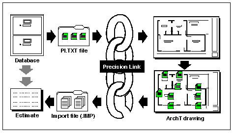
ArchT drawings can be linked to Timberline Precision Estimating software using Precision Link. Precision Link from Ketiv can be used to create complete cost estimates and bills of materials from the CAD drawings. The following figure illustrates how Precision Link works with Precision Estimating and ArchT (Ketiv 1997b).

Figure 1. Integration of ArchT and Timberline Precision Estimating (Ketiv 1997b)
The integration process is initiated in Precision Estimating where the CAD integrator module is used to place the estimating database’s information (work packages, items, and related specifications) in a text file (PI.TXT). Precision Link uses this text file to build a master list of the estimating objects for use with the CAD drawings.
Inside ArchT, Precision Link is then used to assign items and work packages from the master list of estimating objects to assemblies, blocks, or other AutoCAD entities in the drawing. This process tags the CAD objects with Estimating records that contain information about the work packages or items assigned to them. Each CAD object can have one Estimating record assigned to it.
When creating an estimate from the CAD drawing, Precision Link analyzes the Estimating records assigned to the objects in the drawing, and extracts the appropriate information from the Estimating records and puts it in an import text file (.IMP). The import text file is then used to generate the estimate in Precision Estimating.
Value Engineering Analysis of the Exterior Walls of an Office Building
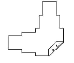
This section describes a value engineering analysis of an office building that was performed using the integrated CAD/Estimating system discussed above. The office building layout is based on one of the designs that are shipped with the ArchT software. Figure 2 shows a plan of the exterior walls of the office building.
Using ArchT, the two-dimensional plan can be changed to a three-dimensional model by creating walls from the existing line entities in the plan. When creating a wall, a wall style that controls its appearance has to be assigned. Several wall styles are pre-defined (e.g. glass curtain walls, brick veneer, stud-wall, etc.) The ArchT user can define new styles if he/she wants to. Styles are also assigned to other ArchT objects such as windows and doors.

Figure 2. Plan of the office building
Estimating records can be assigned to each object style. For example, window style A can have an Estimating record containing information that’s specific to one manufacturer while window style B can have an Estimating record containing information that’s specific to a different manufacturer. This ability makes it easy to insert windows from different manufacturers and to switch the windows from one manufacturer to another.
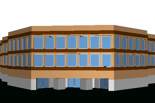
In the VE study of the office building, two exterior wall styles were evaluated with regard to cost and aesthetics. The first wall style was a glass curtain wall. After assigning the style and inserting the walls, doors were added in the building entry. The AutoCAD render module was then used to render a picture of the building as illustrated in Figure 3.
As illustrated in Figure 3, the glass curtain wall style defines the glass as part of the actual wall. The white section of the building is the wall and the dark section is the glass. Using this style, there was no need to add any windows to create the building. The curtain wall style was assigned the "glass curtain wall" record from the Precision Estimating database. Once the estimating record was assigned, all existing walls in the drawing which use the "curtain wall style" were automatically attached to the "glass curtain wall" estimating work package. When the estimate is created using Precision Link, the square foot areas of the walls are extracted from the CAD drawings. These areas are then multiplied by the unit cost that is stored in the estimating database to determine the total price of the wall line item. If the designer later changes the wall objects in the CAD drawing; by changing the height of a wall for example, the estimating records will automatically reflect the new wall height. This capability ensures that the estimate and the design are always in sync with one another.
Figure 3. Rendered image showing first style of exterior walls
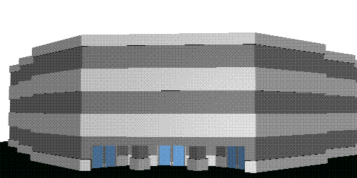
To explore a second design alternative, the "wall style" assigned to the wall was modified to a "brick veneer" style. This was done by simply selecting all walls in the drawing and changing their "style" property. Unlike the first wall style, the "brick veneer" wall style does not incorporate any windows and they had to be added separately. Figure 4- shows the second design alternative. The figure demonstrates how simply selecting a different wall style changes the entire look of a building. Once the wall style was changed, a new estimating record was automatically assigned to the exterior walls of the office building. The estimate was automatically updated to reflect the new record. The cost of the new windows was also reflected in the estimate.

Figure 4. Rendered image showing second style of exterior walls
The Precision Estimating database used in the VE study was the "Conceptual Database". This database is organized into 12 divisions following the UNIFORMAT standard. The UNIFORMAT standard, which is preferred for performing VE studies, breaks down project cost by functional areas such as superstructure, interior construction, etc. If the integrated CAD/Estimating system is to be used for detailed estimating, the estimating database can be changed. This is achieved by simply recreating the PI.TXT file as was previously described.
Conclusion
The ability to integrate Estimating Software and CAD has a great potential for streamlining the value engineering process. Such integration would enable the rapid generation of several design alternatives whose cost and aesthetic appeal can be evaluated and compared for achieving optimum value. This can help the designer with ensuring that cost reduction ideas will not have a negative impact on the aesthetic appeal of the project. The CAD and estimating software available today, with their abilities to link to external programs have made such integration possible.
Streamlining the value engineering process will become more and more important as the popularity of the design/build project delivery system continues to increase. In a design/build contract, the owner enters into an agreement with a single firm to produce all planning, design, and construction with its own in-house capabilities. Improving the accuracy of the conceptual estimate is extremely important in design/build projects because the project price and scope of work usually need to be guaranteed to the client prior to the final drawings and engineering design work. Also, in order to increase their chance of getting the project, design/build contractors need to demonstrate to potential owners the value that they bring to the project through value engineering and constructability analysis.
References
Dell’Isola A. J. (1982). Value Engineering in the Construction Industry. Third Edition, Van Nostrand and Reinhold Co., N. Y.
Elzarka H., G. Suckarieh and R. Dorsey. (1998). Teaching Value Engineering Effectively: An Interdisciplinary Approach. Proc. 34th ann. conf. of ASC. Portland, Maine, pp. 21-28.
Ketiv. (1997a). ArchT Manuals. Ketiv Technologies, Inc. Portland, OR
Ketiv. (1997b). Precision Link Manual. Ketiv Technologies, Inc. Portland, OR
Nashed, Fred. (1996). Time-saver details for exterior wall designs. McGraw-Hill, New York.
Timberline. (1997). Precision Estimating Manual. Timberline Software Corp., Seattle, WA.
Zimmerman, L. W. and Hart, G. D. (1982) Value Engineering: a Practical Approach for Owners, Designers and Contractors. Van Nostrand and Reinhold Co. N. Y.

