(pressing HOME will start a new search)
![]()
![]()
![]()
- ASC Proceedings of the 28th Annual Conference
- Auburn University - Auburn, Alabama
- April 9 - 11, 1992 pp 7 - 12
|
(pressing HOME will start a new search)
|
|
A CLASSROOM EXAMPLE OF HIGHWAY DESIGN WITH CAD
|
|
The state of the art in computerized highway design has evolved faster in the design industry than it has at most universities. Among the limiting factors for many educators are the expense and complexity of highway design software amid shrinking financial support and swelling curricular demands. This paper outlines course development at Bowling Green State University that computerizes the processes of survey note reduction, highway geometric definition and applications, and computer‑generated drawings. The resulting course requires minimal cash investment and classroom effort. The program lacks the higher sophistication of more expensive software but teaches the students through an application process that fosters understanding of the process along with basic computer work. The university does not recommend the software used in this course over any of the competition. However, the cost of the two programs used are less than $200. KEY WORDS: Computer Aided Drafting; Computer Applications in Technology; Highway Design; Route Surveying. |
Highway design in today's computerized offices involves expensive software and hardware that is not affordable for many engineering, technology, and construction programs. Students need to learn a system that transfers elementary surveying notes to computer aided drafting and design program without being overwhelmed. Sophisticated software used by design professionals require weeks to develop rudimentary proficiency and, more importantly, comprehension of the process. The Construction Management faculty at Bowling Green State University have developed a system to teach elementary highway design and incorporate computer aided drafting and design. An important consideration with shrinking education budgets is the software investment is less than $200.
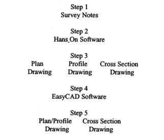
The process, as charted in Table 1, begins with a simple
set of surveying notes, sufficient to challenge, but not overwhelm, a
beginning student. The notes include typical profile elevations, alignment of
the centerline in either azimuth or bearing format, cross section data, and
typical criteria for geometric standards. The data are loaded into a highway
computer program (a shareware called Hans_On) that only requires an
understanding of note keeping formats and some introductory training. The data
is, converted by Hans‑ into drawing, exchange files (.DXF) and uploaded to
a simple CAD program (Easy CAD) where the drawings are refined, combined, and
plotted without the extensive learning curve associated with the more
complicated CAD programs like AutoCAD.
|
|
|
The current state of our universities' budgets does not permit purchases of expensive software. Furthermore, there is little extra time in the curricula and courses of engineering, engineering technology, or construction technology to squeeze a thorough course for high end highway design or computer aided drafting. Our programs already encompass general education, mathematics, surveying, engineering drafting, and highway location and design just to arrive at a point matriculate into a course such as being proposed here in. Another dilemma that must be considered is that various employers, such as departments of transportation and consulting engineers, utilize several different hardware and software combinations, making it very difficult to prepare a graduate who is ready to step into any situation.
The highway design class at Bowling Green concentrates on understanding the operation by first learning the manual operation then applying the computer to the problem. The class saves considerable time and money by operating at the lower end of the cost spectrum, following a simpler "generic" approach. The more sophisticated and expensive software are left to the employers. Thus, students develop a comprehension of the process through the combination of manual operation and computer application, much the same process through which those same computer programs were developed.
The programs being used are Hans‑On and Easy CAD, both IBM compatible programs that are commercially available at reasonable prices. There are many other similarly operating and priced software packages on the market and the selection of those two by BGSU should not be interpreted as a recommendation over any competitor's product. The coursework also involves spreadsheet applications, with the computer laboratory's Lotus 1‑2‑3 being the acceptable spreadsheets.
Hans_On is a surveyor-oriented program intended for secondary road use. It has two significant drawbacks, the first being the lack of an on‑line help system and the other its requirement for EGA or higher graphics. The graphics level, once viewed, seems questionable but becomes moot since CAD graphics at the CGA level are so poor that EGA or VGA is preferred anyway. The other shortcoming is a lack absence of help menus and some rather strange entry protocol, making it necessary to have program documentation alongside the surveying notes for continual referral.
Occasionally, the documentation falls short and supplementary handouts are provided to the students. In spite of clumsy beginnings, students show comfort at the keyboard within the first few hours.
Hans‑On begins as a relatively simple data base into
which the student enters forward azimuths or bearings, elevations, and cross
section data. It is organized into modules and sub‑modules selected from a
menu display. The student must first correctly identify the appropriate disk
drive or output device to be utilized for files, print files, and plot files,
and also select US or metric dimensions. Disk drive letters and subdirectories
must end with a backslash and device ports with a colon, a protocol most other
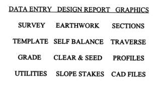
programs don't demand. The modules of the main menu are in Table 2. Only the
Template Module, the Survey Module (briefly described above), and the CAD Files
Module are utilized initially. Highway geometry is entered in the Template
Module, establishing the crown and slope in cut and fill sections. The students
enter surveying data in the Survey Module where their options include azimuths
or bearings, rod readings or actual elevations, and metrics or U. S. Entry
protocol for the cross sections is strict, again, requiring specific keystrokes
in a string entry and the cross section line must intersect the template line on
both sides of the centerline. Results may reviewed and corrected in the
Utilities module along with manual entry of cuts and fills where desired.
Editing must be done in the Utilities Module because the data files are not in
ASCII format to permit use of screen editors. This also precludes the use of
spreadsheet files to generate the initial data. Plan, profile, and
cross‑section drawings are then prepared as drawings exchange files (.DXF)
in the CAD Files Module. These are rather rough drawings that must be edited
outside this program. Drawing development and sample drawings appear later in
this article.
|
|
|
Easy CAD is an inexpensive software that is quickly learned through its pull‑down menus. Users can rapidly upload drawings from Hans_On into Easy CAD and then to other CAD programs. Once the student imports a .DXF drawing into Easy CAD, the convenience of Hans_On and its lower level of graphics output become apparent. The plan views are single lines with no indication of road width. The orientation of the plan view reveals how well the student understood (or guessed) the Hans_On documentation as to which direction is north or up (a prompt at the start of the CAD Files Module). Hans‑On only plots on a Hewlett Packard HP7475 plotter limiting plots to A and B size paper and there are no graphics variables.
DRAWING
DEVELOPMENT
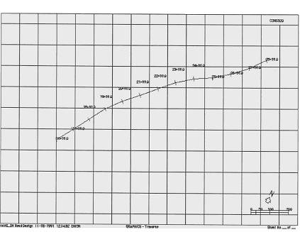
Once the plan drawing file is uploaded into Easy CAD, the student will discover that there are two centerlines, one green and the other red, for existing and proposed (should subsequent work change the horizontal alignment). An example plan view is shown in Appendix A ‑ Figure 1 (larger versions of the drawings are available from the author). During the first exercises the proposed alinement is not important, and one line is erased and the other edited to a centerline style of line. Then road edges and other information are drawn along the road. Superfluous grid lines and program labels are erased. The plan drawing is then edited with an origin (grid coordinates 0,0) along the road (usually the left end) and saved.
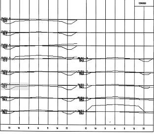
The profile drawing file is then imported, again with it's two lines for centerline elevations. One of the profile lines is erased unless the operator has advanced in Hans‑On to have both existing and proposed profile elevations shown. He or she also erases superfluous grids, program labels, and other unnecessary items. The remaining profile lines are edited to dashed lines to indicate existing elevation. Figure 2 in Appendix A shows the original profile.
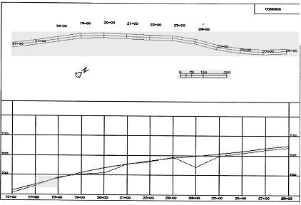
Now the plan view is copied into the upper section of the profile drawing. The sequence is a part insertion that neither changes scale nor rotates the part. Any rotation of the plan view should have been accomplished while that drawing was active. The scale selected during the Hans‑On CAD Files Module determines the number of stations per sheet and remains the same once uploaded into the CAD file. There may have to be multiple insertions to arrange the plan view with the same stations as the profile when dealing with larger projects. Figure 3 in Appendix A shows the new plan‑profile drawing. In the samples herein, a series of vertical curves were edited into the project with the Hans _On Grade Module.
Figure 4 in Appendix A shows the upgraded cross sections drawing. The changes needed from the Hans On output are more corrective in that the program has an error in label alignment. However, as the reader will notice, the cross sections are complete in that existing and proposed elevations are accurate to the revised centerline profile. The upgrading in Figure 4 included changing the existing line style to the more appropriate dashed lines.
The plan/profile drawing is now plotted utilizing a greater selection of plotters and sheet sizes available through Easy CAD. The sample drawings in the figures are not intricate by any measure but demonstrate the basic steps for creating detailed drawings. Additional drawing information and notes are readily. The reader might note that some text in the drawings of the main body of this report appear only as lines.
Once the student has stepped through the process once, he
or she can then return to Hans_On to develop more sophisticated vertical
alignment. The Utilities Module allows for direct input of cut and fill changes
as well as any other design changes. The student may also work in Easy‑CAD
to add drawing details to the plan view, as well as embellish the north arrows
and other features subject to student imaginations. The drawings can also be
exported from Easy‑CAD to AutoCAD to take advantage of its greater variety
of fonts, line styles, and fill patterns.
There are a number of excellent software packages on
the market for teaching highway design in a much more sophisticated manner.
However, until college and university budgets improve considerably, and until
our curricula have significantly more time to devote directly to the technology
of the total process, the use of inexpensive packages such as Hans_On and Easy
CAD can serve the need. The student comprehends the mechanics as he or she uses
these programs so that the manual process and the computerized process are
learned simultaneously. This better prepares them to upload their skills to the
more sophisticated programs upon employment.
Hanson, M. (1988). Hans On
Road Design. Overview and User Guide. Madison, Wisconsin: Hans‑On
Computer Applications.
Oglesby, C.H.
(1990). Dilemmas facing construction education and research in 1990s. Journal
of Construction Engineering and Management. 116 (1),pp.4‑17.
Riddle, S., Montooth, et. al.
(1990). Easy CAD 2 User's Guide. Tempe, Arizona: Evolution Computing. New
York: American Society of Civil Engineers.
Riggs, L. S. (1988). Educating
construction managers. Journal of Construction Engineering and Management.
114(2), pp279‑285. New York: American Society of Civil Engineers.
|
|
|
Figure
1 |
|
|
|
Figure
2 |
|
|
|
Figure
3 |
|
|
|
Figure
4 |